
KAPTEOS PRODUCT LINE
The Value and Benefits of Electro-optic Technology
Kapteos Products
• eoSense™ Optic to Electro Converter
• eoProbe™ to measure E-field (EMF)
•• eoCal™ – eoProbe Calibration
•• eoLink™ – 100m Fiber optic extension
•• eoPod™ – eoProbe Articulated Arm and Stand
Kapteos – On-Site Training
• Applications (Target Markets)
• Antennas – Measurement of E-fields Emitted by Antennas• NFACS (Near Field Antenna Characterization Solution)
• 3D NFACS (Near Field Antenna Characterization Solution)
• Vectorial & Characterization of Ultra Compact Antennas
• EMC -Measurement of E-Fields in Electromagnetic Compatibility
• EMP – Time-resolved measurements of Electromagnetic Pulse
• High Temperature – Measurement in High Temperature
• High Voltage – Measurement of E-fields in High Voltage
• Measuring the E-Field around a Laptop
• MRI – Measurement of E-fields inside an MRI
• Plasma – Measurement of E-fields inside Plasma
• SAR – Specific Absorption Rate (SAR) assessment
• Online Software Simulation Tool – Determine Online, before you purchase, the value of the Kapteos Solution!
• FAQ’s – A wealth of Information!
RELIANT EMC PRODUCT LINES
MANUFACTURERS
Request a Quote / Contact Us!
KAPTEOS APPLICATION SIMULATION
KAPTEOS HAS AN ONLINE APPLICATION SIMULATION TOOL THAT ANSWERS THE IMPORTANT QUESTION OF: «WILL THE KAPTEOS SYSTEM WORK IN MY APPLICATION AND PROVIDE THE DATA I NEED?»
If you are interested in comparing your current E-field measurement solution against the Kapteos solution through their Online application simulation tool, the steps are:
1. Fill out the Online Application Form
2. Prepare for the Simulation by reading the following page
MAIN PARAMETERS TO TAKE INTO ACCOUNT TO PREPARE FOR AN APPLICATION SIMULATION
The measurement of electric fields requires a lot of precaution to ensure valid values. Unlike the measurement of magnetic fields or voltages which are quite well controlled, the measurement of an electric field involves the understanding of the comprehensive performances of the measuring device, the data acquisition system and of course, the application.
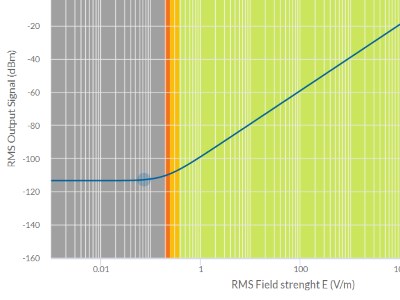
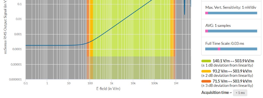 Kapteos graph application simulation output signal
THE UNDERSTANDING OF THE APPLICATION
In one hand, the customer should have some basic knowledge of the expected values to obtain like:
• Min and max values of the electric fields
• Bandwidth of interesting signal
• Single pulse signal or repetitive signal
• Shape of signal
The customer should also know the way to handle the measurement:
• Measurements of the E-fields in time-domain (with an oscilloscope) or in frequency-domain (with a spectrum analyzer) or both
• The performances of its acquisition devices (oscilloscope or spectrum analyzer)
• The various possible settings to improve the performances of the measurements
• The constraints of the measurement inside the applications (EMC, vibrations of the measurement support, temperature variations…)
THE PERFORMANCES OF EOSENSE AND EOPROBE SYSTEM
The eoSense converter provides a laser to the eoProbe that measures the field. The eoProbe reflects the laser back to the optical electronic converter including the signal information. The converter converts the laser information into an analogue electric value proportional to the electric field at any time.
• The general performances of the eoProbe are mainly defined by:
• The bandwidth (approx. 10 Hz up to approx. 50 GHz)
• The sensitivity (depending on the model of the eoProbe)
• The medium of the eoProbe (for air, liquids or gazes)
Example of Application Simulation Output Signal
Whatever the application, the frequency response of the eoProbe is generally the one presented here. This curve, based in an internal simulation tool, does not represent the certified performances of the eoProbe but it is just representing a typical measurement of an electric field
Measurement of E-fields in Medium and high voltage (HV) Magnetic Fields. Normal Configuration:
• eoSense Converter LF (1, 2 or 3 channels. Bandwidth 40Hz~30MHz, 30dB internal amplification)
• eoProbe air probe type with 1 mm or 5 mm of crystal, longitudinal or transverse. Depends on application and investigations.
• Testing: Repetitive pulses or single pulse (partial or total discharges). usually time domain but frequency domain may be sufficient.
Measurement of Electric Fields Emitted by Antennas. Normal Configuration:
• eoSense Converter depends on frequency. Is always with an internal amplifier.
• eoProbe Usually 5 mm crystal longitudinal or transverse
• Testing: Usually CW, so frequency domain.
Measurement of E-fields inside Plasma. Normal Configuration:
• eoSense Converter is usually a MF-01U-G30 always with an internal amplifier (usually 30 dB).
• eoProbe Usually 1 mm crystal longitudinal or transverse
• Testing: Usually repetitive pulses or sometimes CW, so frequency domain.
Measurement of E-fields inside an Magnetic Resonance Imaging (MRI) machine. Normal Configuration:
• eoSense Converter is MF series (64 MHz for 1.5 Tesla MRI and 128 MHz for 3T MRI) always with an internal amplifier (usually 50 dB).
• eoProbe: Usually 5 mm crystal longitudinal or transverse. Usually bio type probe for SAR assessment. · ·
• Testing: Usually repetitive pulses, Frequency domain.
Measurement of E-Fields in Electro-Magnetic Compatibility (EMC). Normal Configuration:
• eoSense Converter depends on frequency (from LF to HF10 or even 18 GHz) always with an internal amplifier.
• eoProbe: Mainly 5 mm crystal longitudinal or transverse.
• Testing: Usually repetitive pulses or sometimes CW, so frequency domain but sometimes time domain.