
MK - MESSTECHNIK PRODUCT LINE
Optical transmission of Analog and Digital Signals
• 1 channel analog – U1/12
• 2 channel analog – U2/12-1M
• 8 channel analog – U8/12-1M
• 16 channel analog – U16/14-100k
Automotive Products
• optoA2B
• optoCAN-FD
• optoCAN-HS
• optoCAN-LS
• optoCAN-SW
• optoFlex
• optoK
• optoLIN
• optoLVDS
• optoPSI5
• optoSENT
• optoSPI
Automotive Ethernet links (T1)
• optoLAN-3xBCM89811
• optoLAN-88Q1010
• optoLAN-88Q2112
• optoLAN-88Q2112
• optoLAN-GB 88Q2112
• optoLAN-GB 88Q2112-MC
• optoLAN-GB 88Q2112-MATEnet STP
• optoLAN-GB 88Q2112-MATEnet STP – MC
• optoLAN-BCM89810
• optoLAN-BCM89811
• optoLAN-TJA1100-MAX
• BroadR-Reach GB media converter HSD
Camera Systems
• dAV-Cr-HD – HD Camera, mono microphone
• dAV-Cr-HD-30-nd – HD with 30x Zoom, mono microphone
• dAV-Cr-HD-mini – HD, 40% smaller, microphone not integrated
• dAV-Cr-HD-µ – HD, 60% smaller, mono microphone
• dAV-Quad 4k / Multiviewer – view 4 channels on one screen
• opto-LWIR – Infrared Camera
• HD-recorder dAV-R option -HDrec – digital recording of HD audio/video channel
• dAV-Rr-HD-TT – receiver in table top housing
• dAV_Cr_SD – Standard Definition Camera, mono microphone
• Options for the Digital Camera System
Tripods, Monopod and Auto Mounts
dAV Transmission, intercom
Digital (LVDS) Transmission
• opto1394 – IEEE1394/Firewire signals
• optoLAN – 100MBit per second
• optoLAN-Gb – 1 GBit/s
• optoLAN – option M12
• optoLAN-BCM89810
• optoLAN-BCM89811
• optoRS232-HS
• optoRS485
• optoTTL
• optoUSB2.0
• optoUSB2.0-RBDIR
• optoUSB3.0
optoLVDS
Power Supply
• BV-10D+-10V
• BV-12D +1 12V
• BV-12S 12V
• BV-15S 15V
• BV-24S 24V
Accessories / Misc
Company Overview
Data Sheets
Product List
RELIANT EMC PRODUCT LINES
MANUFACTURERS
Request a Quote / Contact Us!
MK MESSTECHNIK U3/12 2 CHANNEL ANALOG
mk-messtechnik Us/12 and U2/12-1M 2 channel analog
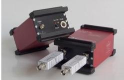
The U2/12 and US/12-1M are used for the optical, digital transmission of up to 2 analog signals with a resolution of min. 8 Bit each channel.
Both U2/12 models consist of a transmitter supplied by an external power supply, a plastic optical fiber, and a receiver – which has an external power supply as well.
Due to the U2/12 models insensitivity to strong electromagnetic fields above the specified transmission range the systems are fit for tests of electromagnetic compatibility in EMC-test chambers, TEM-cells, and striplines. The signal to be measured is filtered, sampled, digitized, and transmitted to the receiver via an optical transmitter system. At the receiver the digital data stream is converted into an analog signal again and can be measured with a high-impedance probe (e.g. an oscilloscope) at the signal output.
The U2/12-1M is availbel in two models:
1. U2/12 10MHz
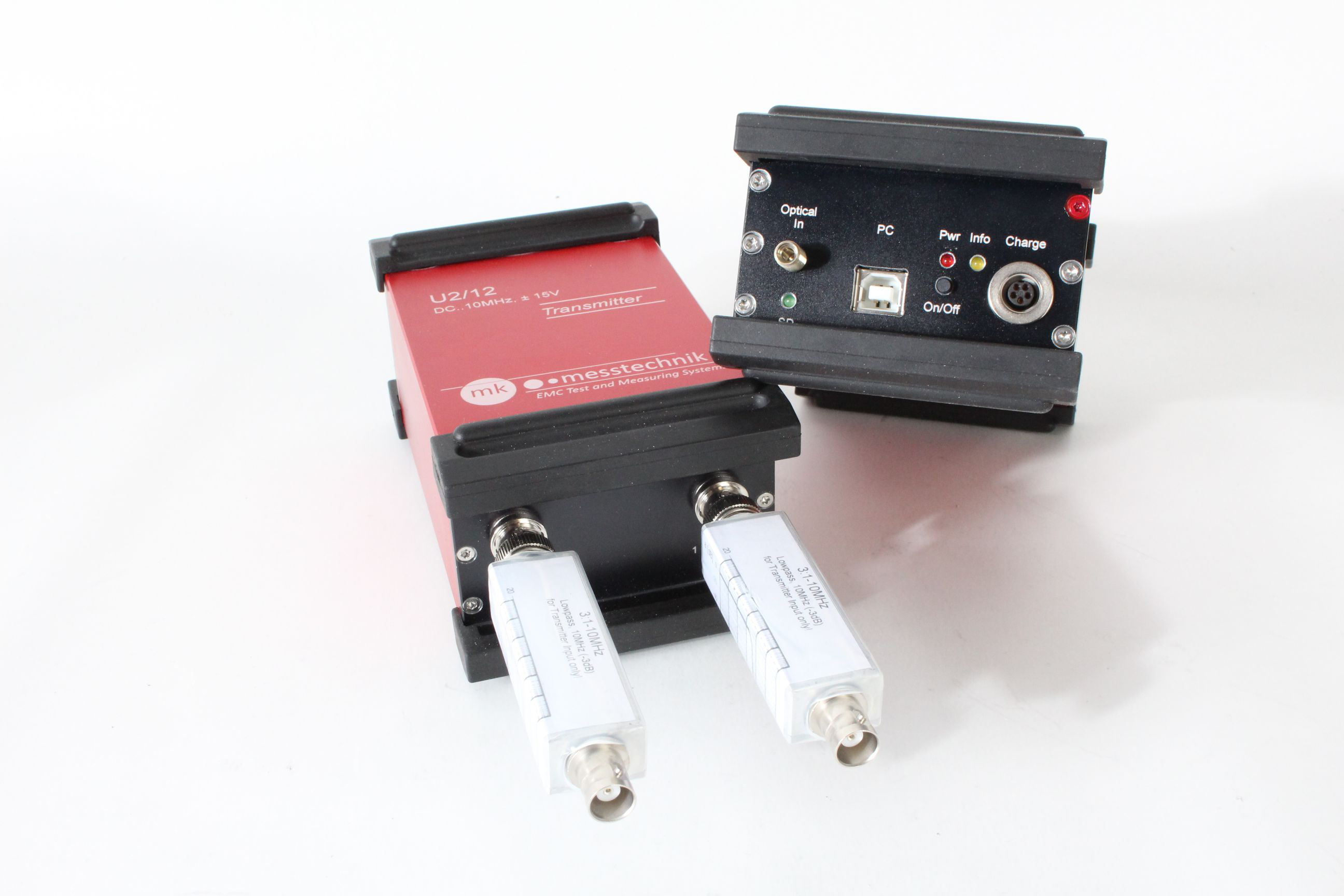
mk-messtechnik U2-12 with input and output filter
2. U2/12-1M 1MHz
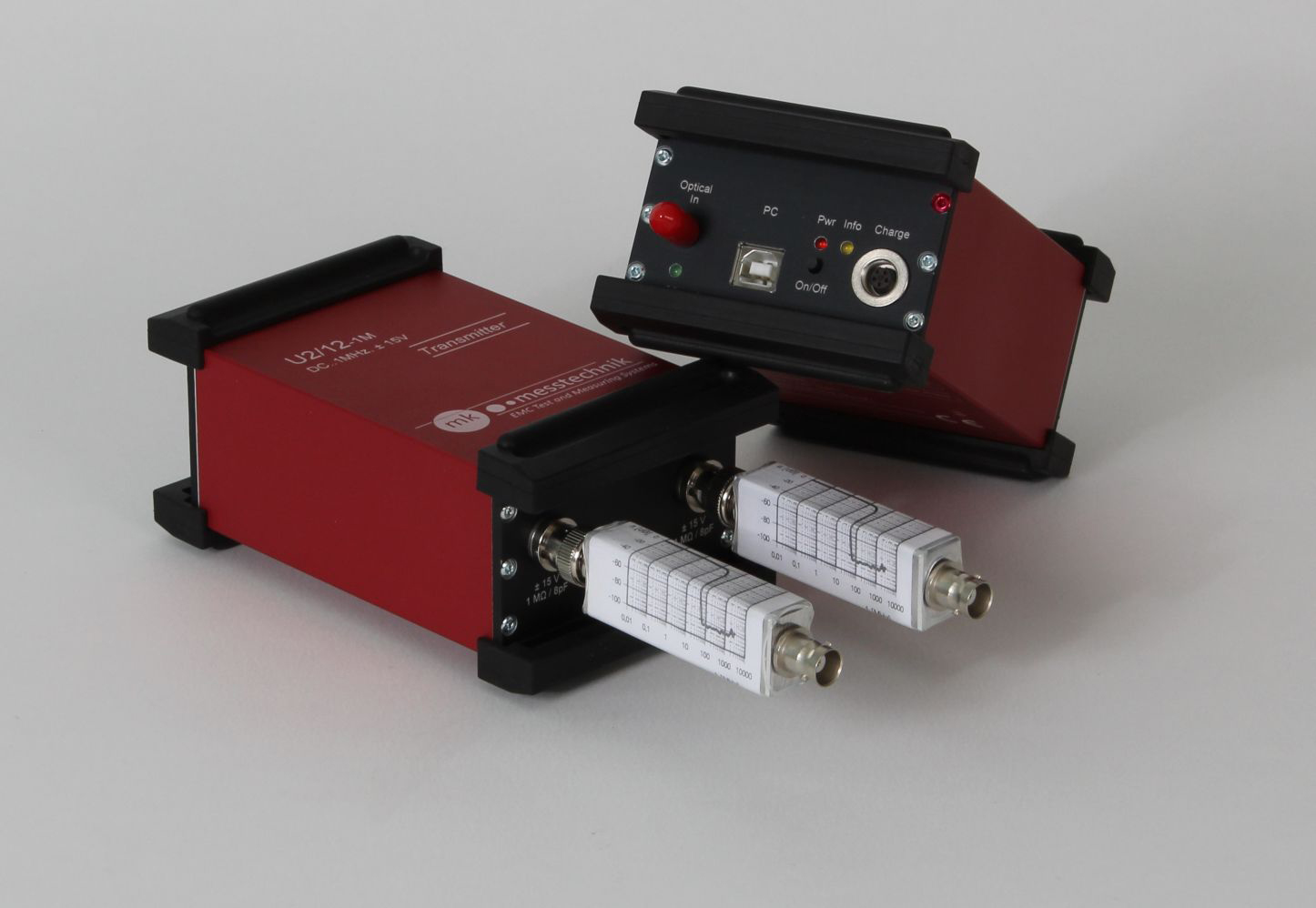
mk-messtechnik U2-12-1M with input and output filters
|
Product |
Voltage Range |
min. eff. Resolution |
Bandwidth |
|
U2/12 |
+/- 15V |
10 Bit |
up to 10MHz |
|
U2/12-M |
+/- 15V |
10 Bit |
up to 1Mhz |
|
Ux/14 (x=up to 16 Channels) |
+/- 15V |
10 Bit |
up to 100Khz |
![]() mk-messtechnik U1/12-1M and U2/12-1M Analog Transmitter Users Manual
mk-messtechnik U1/12-1M and U2/12-1M Analog Transmitter Users Manual
![]() mk-messtechnik U1/12 and U2/12 Analog Transmitter Users Manual
mk-messtechnik U1/12 and U2/12 Analog Transmitter Users Manual