
SPITZENBERGER & SPIES Analog High Performance Amplifiers
Automated Test Systems
Automotive Supply Simulation Systems
Avionic Supply Simulation System
Basic EMC Test System
Battery Energy Storage Systems (BESS)
Car Supply Simulation PAS GN/Kfz
Current And Voltage Sources
• APS – AC/DC – 4 Quadrant Voltage Amplifier
• ACS – AC/DC 4- Quadrant Current Amplifier
• LVA Series Of 2-/4- Quadrant Voltage Amplifiers
• PAS – AC/DC 4- Quadrant Voltage Amplifiers
• DCS – AC Switching Current Amplifier
• EV – AC Voltage Amplifiers
Mains Supply Simulation System
PHIL – The Benefits Of Using SpS Linear Amplifiers In PHIL
PHIL Power – Hardware – In – The – Loop
Photovoltaic Simulators – Test Results For Inverter Test
Railway Supply Simulation System
Test System For BESS For Testing The Characteristic Of Battery Energy Storage Systems
Test System For Magnetic Field Simulation
Test System For Solar Inverters
The Bench For Circuit Breaker Testing
Spitzenberger & Spies-Test Automated
RELIANT EMC PRODUCT LINES
MANUFACTURERS
Request a Quote / Contact Us!
Benefits Of The PAS 4 - Quadrant Linear Power Amplifiers Integrated in PHIL
SPITZENBERGER & SPIES
BENEFITS OF THE PAS 4 – QUADRANT LINEAR POWER AMPLIFIERS INTEGRATED IN PHIL
PHIL ADVANCED SOURCES
THE REAL BENEFITS OF THE PAS 4 – QUADRANT LINEAR POWER AMPLIFIERS INTEGRATED IN PHIL – POWER HARDWARE IN THE LOOP
The real time simulation of complex systems is commonly known using simulator systems from companies like RTDS or OPAL-RT.
With these systems it is possible to set up and model the behavior of real existing electrical systems in a virtual world. The virtual world can be connected with the real world using digital and analog interfaces. These interfaces are mostly a set of output and input terminals for the interaction of the simulation and the real world.
If only signal lines are connected to the external real devices (like sensors and actors) the subsystem is called HIL – Hardware-in-the-loop.
Power-Hardware-in-the-loop (PHIL) simulation means the connection of a physical power device like a power amplifier to a virtual simulation system.
The two main subjects defining the quality and accuracy of a PHIL system are:
1. The delay time between interface output terminal and power output plug of the power amplifier
2. The stability of the system
– the stability of the control loop (interaction between simulation and hardware)
– the electrical stability of the power amplifier’s output signal
THE DELAY TIME
The time difference between the output terminal of the PHIL interface and the relating re- action at the output of the power device is defined as the system’s delay time.
Actual PHIL simulation systems have delay times between 200μs and 3000μs.
Ultra high speed digital connections are able to decrease the delay time down to 15μs range for digital powerless I/O terminals.
With a connected power device typical minimum delay times are in the range of 700μs standard down to 200μs improved systems.
With the PAS amplifier system from Spitzenberger & Spies it is possible to decrease the delay time down to a minimum value of 30μs with AC coupling and below 10μs with DC coupling. With these extra low delay times it is easy to improve the speed of the PHIL system on the power part of the devices up to a factor of 10 in comparison to other systems on the market.
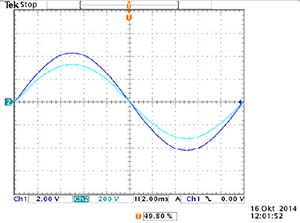
DELAY TIME MEASUREMENT VALUES
Input signal vs. Output signal
Channel 1: direct input of the amplifier (dark blue)
Chanel 2: Amplifier’s output signal (cyan)
Time resolution: 2ms/DIV
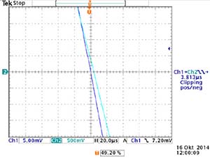
Zoom 1:
Time resolution 20μs/DIV
Measured delay time between input and output 3.813μs
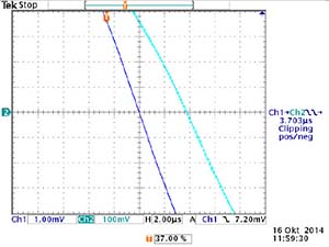
Zoom 2:
Time resolution 2μs/DIV
Measured delay time between input and output 3.703μs
THE STABILITY OF THE OVERALL SYSTEM
Two areas of stability of a PHIL system need to be considered:
On the one hand the regulation loop stability, the interaction between the simulator’s output terminals and the feedback of the connected hardware to the simulator’s input terminals.
On the other hand the speed of the changing of the output signal of the connected power source and it’s stability during supplying a connected EUT.
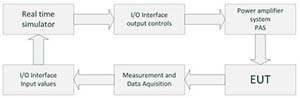
Spitzenberger Spies PHIL Power Hardware in the Loop Diagram
With the very low transition delay time of the PAS amplifier, the combination of a high level simulator with the technical advanced 4-quadrant power amplifiers from Spitzenberger & Spies will lead to the perfect PHIL testing system. The lower the time delay between the adjustment of the simulator output parameters and the feedback of measurement data into the simulator is, the better is the stability of the overall PHIL system. In addition, the system performance increases extensively and the simulation approaches the reality very closely.
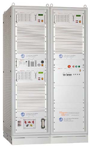
3-phase Grid Simulator DM 30000 for PHIL
THE STABILITY OF THE POWER AMPLIFIER OUTPUT SIGNAL
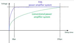
The power amplifier’s output signal stability is depending on the signal rise time, accuracy and the stability of the power source itself. When using standard power sources on the market the
stability of the output signal is often limited to real loads.
Fast changes of the output signal must be carried out slowly to avoid overshooting and instability of conventional power amplifier systems With the PAS amplifier system the power output is always a fast and stable signal even with high non-linear loads, no matter whether they are pure inductive or pure capacitive.
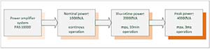
Any type of PHIL EUT’s can be connected. Especially motor-driven components with high initial current consumption can easily be supplied by the PAS. The short-time power capability of the PAS can supply the connected motor with the double nominal power for a time period up to 10 minutes.
Even EUT’S with a capacitive input stage like rectifying bridges with high peak current consumption can be supplied using the peak power capability of the PAS. The PAS peak power capability extends the output power up to 4 times the nominal power for a time period of up to 3ms.
ASSOCIATED DOWNLOADS
![]() Spitzenberger & Spies 4-Quadrant Amplifier type PAS 5000 Data Sheet
Spitzenberger & Spies 4-Quadrant Amplifier type PAS 5000 Data Sheet
![]() IEC/EN 61000-3-2 – Harmonic Performance
IEC/EN 61000-3-2 – Harmonic Performance
![]() IEC/EN 61000-4-11 – Monitoring Measurements and Inrush current source
IEC/EN 61000-4-11 – Monitoring Measurements and Inrush current source