
EMCIS PRODUCT LINE
DC Bias Sources
• DC Bias Source DBS-20D 20A, 10mA steps
• DC Bias Source DBS-50D 50A, 10mA steps
EMI Analyzers
• EA-100
• EA-300
• EA-2100
Filter Analyzers
• FA-2100
• FA-300
Filter Design Kits
• Filter Design Kit FTK-01
• Filter Design Kit FTK-05
LISN
• LN LISN Product Line
Near-Field Probe Kit
Reference Source CRS-1530
Transient Limiter – TL SeriesVisualization Analyzer – VA-100
EMCIS Company Overview
EMCIS Data Sheets
EMCIS Product List
RELIANT EMC PRODUCT LINES
MANUFACTURERS
Request a Quote / Contact Us!
EMCIS EMI Filter Analyzer FA-2100
Filter Analyzer FA-2100
• Analysis of EMI Filter Insertion Loss in Differential-mode and Common-mode
• Easiest and Accurate Quality control of filters and its components, Inductors, and Capacitors
• Powerful instruments to design and development of EMI Filters
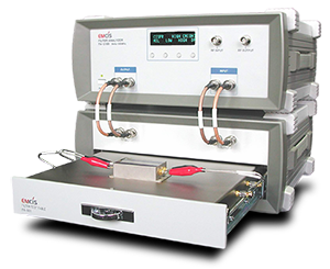
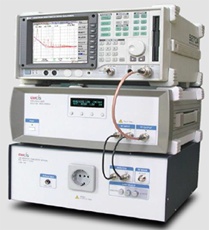
EMCIS FA-2100 Filter Analyzer
Characteristics
• Capable of measurement to meet the regulation of CISPR17
and MIL-STD-220B.
• Wider range of measurement from 9kHz up to 300MHz
• Analysis and measurement of insertion loss in Differential and Common-mode separately and respectively
• EA-2100 can be used any brand of spectrum analyzer and
Network Analyzer now being used on the field.
– minimizing investment cost
– maximizing the capability of the used instruments
• Quality control capabilities of EMI filter components like Common-mode & Differential-mode choke coil, Y-capacitor, and X-capacitor in their insertion loss function.
• Capable to design and develop EMI filters and Inductors in quality controlled.
• Most efficient quality control in mass production by using
insertion loss characteristics measured by FA-2100
Main Function
•Upgraded capability covering wider frequency range ;
– Full range of Conducted ; up to 30MHz
– major field of Radiated ; up to 300MHz
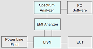
•Set up the line
– Connect Signal Output of LISN to Input of EA-2100
– Connect Output of EA-2100 to Input of spectrum analyzer/EMI receiver
•Operation
Operating by push-button on front panel
– Simply and Easy
Selecting the Measurement Modes ; Test and Analysis
– Test Mode : measurement of L1 and L2
– Analysis Mode : Differential and Common-mode
Selecting the Noise Modes ; L1, L2, DM, CM
– LOW ; for Conducted range (9KHz ~ 30MHz)
– HIGH ; for Radiated field (30MHz ~ 300MHz)
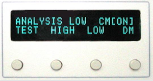
Control button and Display
Noise Analysis
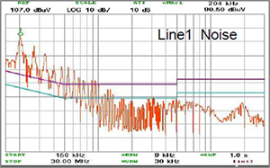
Line 1 Noise Chart
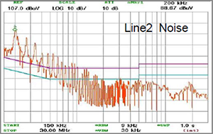
Line 2 Noise Chart
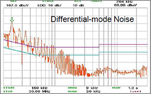
Differential Mode Noise Chart
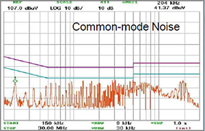
Common Mode Noise Chart
System Configuration
Options
Filter Test Table FA-001
Associated Downloads
Associated Downloads
Associated