
GTEM ITALIA PRODUCT LINE
GTEM-CCC-100 Capacitive Coupling Clamp
GTEM – Cell Home Page
• Specifications Matrix for all GTEM Models
• GTEM – 250 F Family – 250 A-F, A-F-V, 250 A-F-SAE, A-F-V-SAE
GTEM – 400 Family – 400 A, 400 K, 400 A-K
• GTEM – 450 Family – 450 A, 450 K, 450 K-A, 450 A-V, 450 K-V, 450 K-V-A
• GTEM – 550 F Family – 550 A-F, 550 K-F, 550 A-F-V, 500 K-F-V
• GTEM – 750 Family – 750 A, 750 K
• GTEM – 800 Family –800 A,800 K,800 A-F,800 K-F
• GTEM 1000 K
• GTEM 1100 Family – 1100 K, 1100 K-F
• GTEM 1250 K
• GTEM 1300 K
• GTEM 1500 K
• GTEM 1600 K
• GTEM 1750 K
• GTEM 1800 K
• GTEM 2000 K
• GTEM 2100 K
• GTEM 2500 K
• GTEM 2600 K
Accessories for GTEM Cells Matrix
TEM Cells
• TEM 200 Data Sheet
• TEM 500 Data Sheet
• TEM 1000 Data Sheet
• TEM 3000 Data Sheet
Open TEM Cells
• O-TEM 220 Data Sheet
• O-TEM 500 Data Sheet
• O-TEM 1000 Data Sheet
• O-TEM 3000 Data Sheet
Reverberation Chambers
REVERBERATION TENTS
Shielded Chambers
STRIPLINE FOR IMMUNITY TESTS Mod. EMC-STPL
Stirrer to reduce inhomogeneous (standing waves) in reverberation chamber
GTEM ITALIA Company Overview
GTEM Italia Data Sheet
GTEM Italia Product List
RELIANT EMC PRODUCT LINES
MANUFACTURERS
Request a Quote / Contact Us!
GTEM CELL 250F FROM GTEM ITALIA
The GTEM 250 F (F for Ferrite tiles) Family from GTEM Italia are designed for testing to IEC/EN 61000-4-20, SAE J1752/3, IEC 62132-2 and IEC 61967-2.
The GTEM 250 F Family with Ferrite tiles on the bottom offers a wider operating bandwidth with peak smoothed and flat response starting from DC to microwave frequencies.
It is an indispensable tool for researchers and developers engineers!
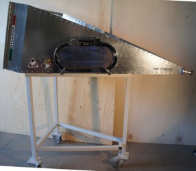
GTEM Italia GTEM 250 F in Horizontal Orientation
There are four models of the GTEM 250 available:
|
GTEM 250 A-F |
Shipped Assembled. With Ferrite tiles. |
|
GTEM 250 A-F-V |
Shipped Assembled. With Ferrite tiles. Vertical Orientation. |
|
GTEM 250 A-F-SAE |
Shipped Assembled. With Ferrite tiles. With SAE Opt. |
|
GTEM 250 A-F-V-SAE |
Shipped Assembled. With Ferrite Tiles. Vertical Orientation. With SAE Opt. |
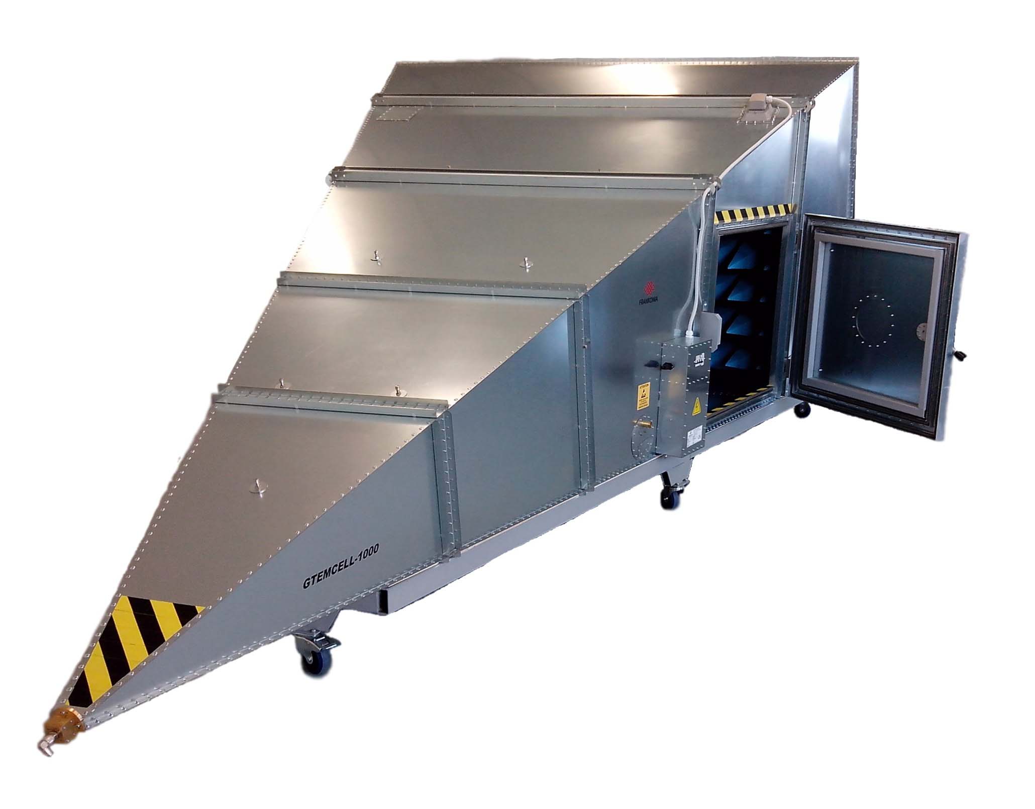
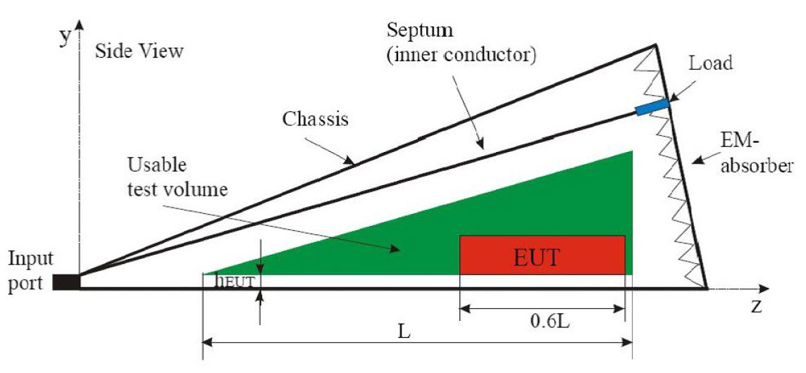
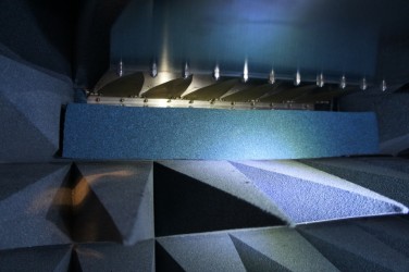
The GTEM cell is, in principle, a tapered coaxial line (offset septum plate), which is terminated by a hybrid combination of discrete resistors and RF absorbers to achieve a 50 Ohm broadband match. It is applied for the Measuring of Emission, Radiated, radio frequency field-immunity test.
The GTEM250 Family utilizes Ferrite tiles on the bottom to provide a wider operating bandwidth with peak smoothed and flat response starting from DC to microwave frequencies.
GTEM 250 A-F-SAE and GTEM 250 A-F-V-SAE
Both of the SAE Models (GTEM 250 A-F-SAE and GTEM 250 A-F-V-SAE E) include a special opening to test integrated circuits.
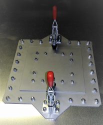
The standards SAE J1752/3 and IEC 61967-2 define a method for measuring the electromagnetic radiation from an integrated circuit (IC). The IC itself is mounted on a test board on a panel that is clamped in the upper face close to the top of the GTEM cell. The test board becomes a part of the cell wall.
A receiver or spectrum analyzer measures the RF emissions emanating from the integrated circuit and impressed onto the septum of the cell. The standard IEC 62132-2 defines the immunity test set-up on integrated circuits tested with a GTEM.
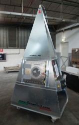
Both the GTEM 250 A-F and GTEM 250 A-F-SAE GTEM Cells can be ordered in a Vertical orientation!!!
Great Space Savings orientation!
GTEM-250 Power requirement
|
Field Strength E |
Flatness |
Modulation allowance |
Required power modulated |
Required power CW |
|
V/m |
3dB = 2 |
80% AM, 1kHz |
Watts |
Watts |
|
3 |
2 |
3,24 |
0,073 |
0,0225 |
|
10 |
2 |
3,24 |
0,81 |
0,25 |
|
30 |
2 |
3,24 |
7,29 |
2,25 |
|
100 |
2 |
3,24 |
81 |
25 |
Main Technical Specifications / Max EUT Size
|
Frequency range |
For emissions: 9KHz – 3 GHz For immunity applications: 80MHz – 6GHz * DC-20GHz optional |
|
Septum Height [mm]: |
250mm |
|
Max EUT Size (LxWxH)cm |
20x20x15 cm. |
|
Defined test Vol. within 6dB |
8.3×8.3×8.3 cm. |
|
Typical VSWR |
1:1.2 (for immunity test range) |
|
Typical VSWR at critical frequency |
<1:1.6 (for immunity test range) |
|
Max Input power, W continuous/*pulsed |
1 kW/2.5 kW |
|
Input connector |
7/16“ or N UG-21 |
|
Nominal impedance |
50 Ohm |
Mechanical Dimensions
|
Outer LxWxH [cm]: |
125 x 64 x 44cm |
|
Door WxH [cm]: |
Standard: 20 x 30cm |
|
Window in the door (WxH) |
* Optional: 24x14cm |
|
Weight Kg. Approx. |
Approx. 35kg |
|
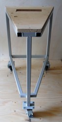
Wheeled undercarriage (with brakes) |
* Optional: 75cm, high |
Electrical Specifications
|
Mains connectors |
Fix/CEE |
|
Main switch |
magneto-thermal 16A mono phase |
|
Input socket plug |
16 AC IEC Type ( mono phase + ground) |
|
Output socket EUT tape |
16 AC SHUCO type (mono phase + ground) |
|
Additional EUT sockets |
* Optional |
|
Ground connection |
M6 bolt,(it is required be always connected) |
|
EMI AC Line filter (mono phase + ground) |
16A 250V n.2 terminals +ground |
|
Channel for fiber optic leads |
3 couples (18GHz Cut-off frequency) |
|
RF feed-thru connector |
N.1 N-N female |
|
RF feed-thru SMA connectors |
N.2 SMA-SMA female |
|
Technical panel pre-drilled for options |
supplied |
Options
|
Midia filter unit |
*Optional: N.1 RJ45, N.1 DB9-RS232, N.2 USB-2, N.1 |
|
Wheeled undercarriage |
|
|
Video camera system |
M6 bolt,(it is required be always connected) |
|
Indoor lighting |
10W LED |
 GTEM Italia GTEM 250 Data Sheet
![]() GTEM Italia GTEM 250 SAE Option Data Sheet
GTEM Italia GTEM 250 SAE Option Data Sheet
![]() GTEM Italia GTEM 250 1000 Specifications Matrix Data Sheet
GTEM Italia GTEM 250 1000 Specifications Matrix Data Sheet
![]() GTEM Italia TEM Cell Typical Power Requirements Data Sheet
GTEM Italia TEM Cell Typical Power Requirements Data Sheet
![]() GTEM Italia GTEM Differences Than Competitors Data Sheet
GTEM Italia GTEM Differences Than Competitors Data Sheet
![]() GTEM Italia GTEM Fans Data Sheet
GTEM Italia GTEM Fans Data Sheet
![]() GTEM Italia GTEM Fans Channel Data Sheet
GTEM Italia GTEM Fans Channel Data Sheet
![]() GTEM Italia GTEM Options and Accessories Matrix
GTEM Italia GTEM Options and Accessories Matrix
![]() GTEM Italia GTEM Shielded Honeycomb Air Vent Data Sheet
GTEM Italia GTEM Shielded Honeycomb Air Vent Data Sheet
![]() GTEM Italia GTEM Shielded Honeycomb Air Vent Diagram Data Sheet
GTEM Italia GTEM Shielded Honeycomb Air Vent Diagram Data Sheet
![]() GTEM Italia GTEM Test Volume Data Sheet
GTEM Italia GTEM Test Volume Data Sheet
![]() GTEM Italia TEM Cell Analysis of the Field Homogeneity Data Sheet
GTEM Italia TEM Cell Analysis of the Field Homogeneity Data Sheet