
SCHWARZBECK PRODUCTS
• Accessories
• Antennas
• Antenna Adapter, Masts, Telescopes and Wheels
• Attenuators And Pulse Limiters
• Baluns
• Blocking Filters
• CDN´s
• CDNE
• Clamps: Abosorbing, Injection And Capacite Coupling Clamps
• Coaxial Cables
• Comb Generators / Reference Radiators
• Dummy Lamps
• Electromagnet
• Field Meters
• Helmhotz Coils / Radiating Loops
• LISN Line Impedance Stabilization Networks / AMN Artificial Mains Network
• BAN Broadband Artificial Networks Acc. To ISO 11452/7 Or DC-10614
• MagTest System
• Near Field Probes
• PLC – Devices Acc. To En 50561-1
• Preamplifiers
• Pulse Generators
• Striplines / TEM – Cells
• Spectrum Generator
• Used Equipment
• Van Der Hoofden Test Head
• Voltage Probes
SCHWARZBECK Company
SCHWARZBECK Data Sheets
SCHWARZBECK Product List
RELIANT EMC PRODUCT LINES
MANUFACTURERS
Request a Quote / Contact Us!
Automotive Toyota LISN
Schwarzbeck Toyota Single path low-impedance AMN Automotive LISN
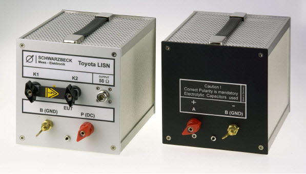
The main application of the unsymmetrical single path AMN (artificial mains network) Toyota LISN is the measurement of interference voltages in the frequency range from 10 kHz to 150 MHz for automotive purposes according to Toyota standard TSC7042G.
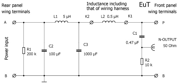
An external coil has to be connected to the terminals K1 and K2 (Fig. 1). The inductance of L2 should be adjusted so that the total inductance of L2 and the connected cable (terminal P to EuT) equals 0.5 μH.
The impedance characteristics are basically realized by connecting an inductor in parallel with the input impedance of the measurement receiver: 0.5 μH || 50 Ω.
|
Specifications: |
|
|
FrequencyRange: |
10 kHz – 150 Hz |
|
Max. cont. current: |
70 A |
|
Max. current (limited time) |
100 A |
|
Max voltage (DC) |
200 V |
|
Impedance: |
(0.5 µH) || 50 Ω |
|
DC-Resistance mains-EuT: |
<5 mΩ |
|
Measuring port: |
N-connector |
|
EuT connectors: |
Screw terminal, see photo |
|
Dimensions (W x H x D): |
160 x 165 x 210 mm |
|
Weight: |
2.8 kg |
|
According to standard: |
Toyota TSC7042G |
Fig. 1. Principle circuit diagram of the Toyota LISN
Interference voltage measurements
The device under test has to be connected to the terminal P at the front panel. The supply voltage has to be connected at the back panel. The 100 μF capacitor located at the backside is connected to ground. The RF-interference voltage emitted by the equipment under test can be measured at the N-connector using an EMI receiver.
Please note: The injected RF-power passes from the EuT-terminals directly to the Nconnector without any attenuation. Eventually connected RF-measuring equipment may be damaged!
The device under test may drain a continuous current of 70 A and for a short period of time it may even drain more than 100 A.
A sufficient air-circulation must be provided to avoid overheating of the LISN.
Do not cover the LISN! The top and bottom hole-plates must not be covered to provide good air circulation.
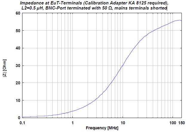
Impedance at EuT-Terminals (Calibration Adapter KA 8125 required), L2=0.5 μH, BNC-Port terminated with 50 Ω, mains terminals shorted
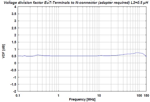
Voltage division factor EuT-Terminals to N-connector (adapter required) L2=0.5 μH
Heat up characteristics at continuous currents

![]() Schwarzbeck Toyota Single path low-impedance AMN Automotive LISN Data Sheet
Schwarzbeck Toyota Single path low-impedance AMN Automotive LISN Data Sheet