
Schlöder Product List
Schlöder- ESD Simulators
• SESD 216 ESD Simulator 16,5 KV
• SESD 230 ESD Simulator 30 kV
• SESD 30000 EDS Simulator 30 kV
• SEDS 2910 ESD – Test System 30 KV
Schlöder- EMC Generators / Measurement System
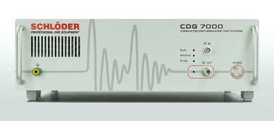
• CDG 7000 Conducted Disturbances Test System
• CWG 1500 Surge / Hybrid Generators
• CWG 2500 Surge / Combination Wave Generators
• MGA 1033 Magnetic Field Generator And Analizer
• CAL 1250 Magnetic Field Calibrator
• PG 01-2000 Pulse Generator
• PGA 1240 Immunity DC – 300 kHz
• PGA 1240-5A & PGA 1240-16A Power DC Generators
• PGA – 1330 Immunity Generator
Schlöder- Burst Generators
• SFT 1400 Burst Generator 125 KHZ
• SFT 1420 Burst Generator 2 MHZ
• SFT 2400 EFT/Burst Generator 2 MHZ
• SFT 2420 EFT/Burst Generator 2 MHZ
• VIS 1700 Voltage Interruption Simulator
Schlöder- CDN – Coupling Decoupling Networks
Schlöder- Coupling Networks For Burst & Surge
-CN 1240-32 And CN 1240-125 Coupling Switchable Networks
-Mains Operation 3-Phase
• CWG 520
• CWG 523 / CWG 523-550
• CWG 524 CWG 524-550
• CWG 524-B / CWG 524-B-550
Interconnection Lines / Surge test only
• CWG 1525
• CWG 1526
• CWG 1528
Schlöder Current Monitoring Probes
• CDG CMP-45 Current Monitoring Probe
• CDG CMP-46 Current Monitoring Probe
• CDG A CMP-46 Calibration Set for the CDG CMP-46 Current Monitoring Probe
Schlöder- Accessories
-Burst Generator Accessories
• CWG 520 – 3-phase coupling network, 4 x 16 A – Burst and Surge
• CWG 523, CWG 523-550, CWG 524 CWG 524–550 – 3-phase Coupling Network, 4 x 32 / 60 A – Burst and Surge
• CWG 524-B – 3-phase Coupling Network, 4 x 60 A – Burst only
• EMV-SOFT – Remote control software for SFT, CWG, VIS
• SFT 415 – Capacitive Coupling Clamp (CCC)
• SFT 415-1 – Capacitive Coupling Clamp with protection cover
• SFT 415-CS – Calibration Set for verification the CCC
• SFT 430 HV Cable for Burst Generator
• SFT 450-Set – Attenuator Set
• SFT 470 – Probe set for Burst generator to create short time magnetic fields
ESD Simulator Accessories
• SESD 271 – Vertical Coupling Plate
• SESD 272 – Earth Cable
• SESD 30 S 120 – ESD Remote Control Software
• SESD 30 T 1000 – Support Arm with Balancer
• SESD 3020 – SESD 3027 – Test Tip´s for ESD
• SESD 3036 – Hook for Balancer
• SESD 8800-4 – ESD Target 4GHz
Surge / Hybrid Generator Accessories
• CWG 520, CWG 520 / 550 – 3-Phase Coupling network
• CWG 523, CWG 523-550, CWG 524, CWG 524-550- Coupling networks for Burst and Surge testing
• CWG 550 – External 18 µF capacitor in a housing
• CWG 553 – External 0,5 µF capacitor + 40 Ohm resistor in housing
• CWG 554 – External 9 µF + 10 Ohm resistor in housing
• CWG 1525 – CDN for 2 unshielded, balanced signal lines, 1 A, with gas discharger arrester
• CWG 1526-4, CWG 1526-10 – CDN for 2 unshielded, unbalanced data – and signal lines, 4 A or 10 A
• CWG 1528 – CDN for 4 unshielded, unbalanced data – and signal lines, 6 A, with RS 232 interface
• EMV-SOFT – Control software for SFT, CWG and VIS generators
Immunity, 10 kHz – 230 MHz Accessories
• CDN xxx -Coupling/Decoupling
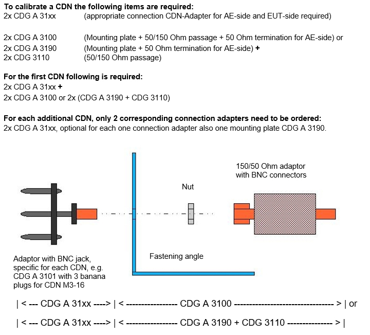
• CDG A 31xx – Calibration adapters for CDN’s
• CDN-EMCL-20 & CDN EMCL-35 – EM Clamps
• CDN ABCL-20 – Decoupling Clamp
• CDN EMCL-NW_10 – Matching Network
• BCI-P1 – Clamp Bulk Current Injection (BCI) with Calibration Set
• CDG CMP-45 – Current Monitoring Probe With Calibration Set
• CDG CMP-46 – Current Monitoring Probe
• CDG A CMP-46 – Calibration Set
• CDG 6050 – 6dB Attenuator, 20W
• CDG 6050-100W – 6dB Attenuator, 100
Immunity, DC – 150 KHZ Accessories
• CN xxx - Coupling Networks
• CN 1240 xx - Coupling networks, switchable
Magnetic Field Generator Accessories
• CMGA_HCST - Helmholtz Coils
• MGA_LS/RL - Loop Sensor
• MGA_Bx - Test adapter, EN 55103
Voltage Interruption Simulator Accessories
• VIS 740 Step Transformer
• EMV-SOFT - Control software for SFT, CWG and VIS generators
Schlöder- Helmholtz Coils
Schlöder- Signal Generator SG 0282
Schlöder- Isolation – Transformers With Double Shield Winding
Schlöder Power Frequency Magnetic Field Immunity Tests
• Schlöder MGA_BC-500 Field Coil acc. to EN 55103-2
• Schlöder MGA 1030 Magnetic Field System Data Sheet
• Schlöder MGA 1030 Magnetic Field Generator and Analyzer Additional Equipment Data Sheet
Products By Standars
RELIANT EMC PRODUCT LINES
MANUFACTURERS
Request a Quote / Contact Us!
CDG 7000 Conducted Generators
NEW! Introducing the CDG 7000 for conducted immunity tests based on IEC 61000-4-6 / BCI
With a 3-channel RF voltmeter, a new signal generator (4kHz-1.2 GHz) and a extended, 3 year warranty, the CDG 7000 builds on, and surpasses the previous CDG 6000 model.
This combined IEC 61000-4-6 system that includes the RF signal generator, an RF-power amplifier, a 3-channel RF voltmeter and a directional coupler is available at a very reasonable price compared to the competition!
Schlöder CDG 7000 Conducted RF Generators
IEC / EN 61000-4-6
ISO 11452-4
Overview
New test generator for all interference immunity standards against conducted Interference induced by high frequency fields – including BCI tests (ISO 11452-4).
One of the very few combined IEC 61000-4-6 test systems that include the RF signal generator, a RF-
power amplifier, a 3-channel RF voltmeter and a directional coupler for a very reasonable price.
The CDG 7000 generates interferences as defined in IEC / EN 61000-4-6 – immunity to conducted
disturbances induced by radio-frequency fields. The standard describes a test setup in which these high-frequency interferences can be influenced on a EUT without a complicated structure with antennas,field instrumentation and shielded rooms. By using coupling networks and coupling clamp’s sine waves are induced directly into power and signal lines. The test object retains its original place in the device structure, so that the system can be tested in its overall function.
Key Facts
– The compact device consists of a RF signal generator, a RF-power amplifier, a 3-channel RF voltmeter And a directional coupler
– Frequency range (signal generator) 4 kHz – 1200 MHz
– The RF power amplifier is available in three different models
– The included application software (HELIA 7 – Basic) enables extensive reporting functions and EUT Monitoring, (HELIA 7 – BCI required for BCI testing)
– Simple expansion with external amplifier via 2nd generator output
– SCPI command set enables easy integration into own software systems
– Interfaces: USB, LAN, GPIB (option)
– Temperature measuring input, e.g. for monitoring and displaying the BCI clamp temperature
– Input for external pulse modulation
– Configurable, digital 8-channel user port
– Warranty 3 years
CDG 7000 Models and Options
| Model | Technical Specifications |
| CDG 7000-25 | Conducted RF generator, acc. IEC 61000-4-6 100 kHz – 250 MHz, amplifier 25W Maximum test level: 10 V (15 V) with 80% AM (without 6 dB) Built-in directional coupler, with software HELIA 7 – Basic USB, LAN |
| CDG 7000-75 | Conducted RF generator, acc. IEC 61000-4-6 100 kHz – 400 MHz, amplifier 75W Maximum test level: 30 V (40 V) with 80% AM (without 6 dB)Built-in directional coupler with Software HELIA 7 – Basic USB, LAN |
| CDG 7000-75-10 | Conducted RF generator, acc. IEC 61000-4-6 10kHz – 250 MHz, amplifier 75W Maximum test level: 30 V (40 V) with 80% AM (without 6 dB)Built-in directional coupler with Software HELIA 7 – Basic USB, LAN |
| HELIA 7 – BCI | Software extension necessary for BCI tests, requires HELIA 7 – Basic |
| CDG 7 GPIB | GPIB interface for CDG 7000 series, NI’s GPIB interface delivers performance, reliability and productivity in measurement technology |
| RF-Power Amplifier | 25 W | 75 W | 75 W / 10k |
| Frequency range | 100 kHz-250 MHz | 100 kHz-400 MHz | 10 kHz-250 MHz |
| Output Power: | |||
| Nominal | 25 W | 75 W | 75 W |
| Linear @ 1dB compression | 20 W | 50 W | 50 W |
| Gain | 46 dB nominal | 51 dB nominal | 51 dB nominal |
| Flatness | ±1.5 dB maximum | ±1.5 dB maximum | ±1.5 dB maximum |
| Input power for rated output | 1 mW / 0 dBm | 1 mW / 0 dBm | 1 mW / 0 dBm |
| Input / output impedance | 50 Ω | 50 Ω | 50 Ω |
| Input VSWR | 1.5 : 1 max. | 1.5 : 1 max. | 1.5 : 1 max. |
| Harmonic distortion | < -20 dBc@ 20 W | < -20 dBc@ 50 W | < -20 dBc@ 50 W |
| Noise figure | typ. 5 dB | typ. 7 dB | typ. 7 dB |
| Spurious output | < -75 dBcat 10 W | < -75 dBcat 10 W | < -75 dBcat 10 W |
Technical Details I
| Module | |
| RF GENERATOR | |
| Two switchable outputs (only one can be used simultaneously) | 2 x SMA |
| Frequency range | 9 kHz to1.2 GHz (usablefrom4 kHz) |
| Frequency resolution | 1 Hz |
| Output level range | 0 to -63 dBm |
| Output level resolution | 0.1 dB |
| Harmonics | < 30 dBc |
| Spurious | < 45 dBc |
| Amplitude modulation(internal) | 0 to100%, resolution1% |
| Amplitude modulation (external) | 0 to 100% , max. Amplitude 1V = 100%, BNC jack |
| Pulse modulation(internal) | 5 to 95%, resolution 1% |
| Pulse modulation(external) | DC…1 MHz, 3,3/5V CMOS/TTL, BNC jack |
| LF-GENERATOR (modulation) | |
| Connector | BNC jack |
| Frequency range | 1 Hz to 100 kHz |
| Frequency resolution | 0.1 Hz |
| Signal | Sine wave / square wave / triangular |
| Amplitude | 0…1 V |
| RF-VOLTMETER 1 (test level) | |
| Connector | BNC jack |
| Frequency range | 9 kHz to 1.2 GHz (usable from 4 kHz) |
| Measuring range | -40 to +30 dBm |
| RF-VOLTMETER 2+3 (forward and reverse power) | |
| Connector | 2 x SMA |
| Frequency range | 9 kHz to 1.2 GHz (usable from 4 kHz) |
| Measuring range | -40 to+ 33 dBm+ directional coupler(typ. 40 dB) |
Technical Details II
| Module | |
| EUT-MONITOR INPUT | |
| Input voltage | 0 to 10 V DC |
| resolution | 2.5 mV |
| Input impedance | 100 kᘯ |
| EUT-FAILED INPUT | |
| Input signal | 3,3/5V CMOS/TTL level |
| Detection mode | status or edge controlled |
| Temperature measurement | 10 to100 °C (1039 to1385 ᘯ) resolution< 1 °C (PT 1000) |
| SCPI Interfaces | |
| USB 2.0 | USB-B |
| LAN, 100 Mbit | RJ45 |
| GPIB (optional) | Centronics |
| Digital I/Os | |
| Out | 4 Bit Digital out, 5 V CMOS/TTL |
| In | 4 Bit Digital in, 5 V CMOS/TTL |
| INTERLOCK | |
| Closes at | R < 1 kᘯ |
| General data | |
| Temperature range | 0 to 40 °C |
| Housing / weight | 19“ desktop case (84 TE; 3 HE) / approx. 11 kg |
| Width / height / depth | app. 450 / 135 / 504 mm |
| AC Input | 100 -240 VAC; 50/60 Hz |
Coupling Networks (special CDNs upon request)
| •CDN M1 |
| •CDN L1-16 |
| •CDN M2-16/32 |
| •CDN M2-32/63/100-HV |
| •CDN M2+3-16/32 |
| •CDN M3-16/32 |
| •CDN M3-32/63/100-HV |
| •CDN M4-16/32 |
| •CDN M4-32/63/100-HV |
| •CDN M5-16/32 |
| •CDN M5-32/63/100-HV |
| •CDN CAN-BUS |
| •CDN AF2/ AF3/ AF4 / AF5/ AF8/ AF12 |
| •CDN T2/T4/T8 |
| •CDN RJ11/RJ45 |
| •CDN S1/ S2/ S3/ S4/ S8/ S9/ S15/ S25 |
| •CDN RJ45S |
| •CDN USB 3.0 |
| •CDN USB-C / USB-P |
| •CDN HDMI |
| •CDN Fire wire |
| •CDN D 100 |
CDN EMCL-20
• EM-Coupling clamp for cables up to Ø 20mm
• Included calibration set and factory calibration
• Option: With matching network CDN-EMCL- NW_10 starting from 10 kHz
CDN EMCL-35
• EM-Coupling clamp for cables up to Ø 20mm
• Included calibration set and factory calibration
CDN ABCL-20 (Absorbing clamp)
• For cables up to Ø 20mm
• For additional decoupling at immunity testing according to IEC / EN 61000-4-6
CDN Calibration set
• Mounting angle: CDG A 3100 (Mounting angle, 50 /150 Ω adapter, 50 Ω Termination)
• Calibration adapter: CDG A 31xx
CDN BCI-P1
• Clamp for Bulk Current Injection (BCI)
• Frequency range 1 – 400 MHz
• For cables up to Ø 40mm
• Included calibration set
CDG CMP-45
• Current monitoring probe 10 kHz – 400 MHz, fold able
• For cables up to Ø 45mm
• Option: Calibration set CDG A CMP-45
CDG CMP-46
• Current monitoring probe 10 kHz – 400 MHz, not
fold able
• For cables up to Ø 46mm
• Option: Calibration set CDG A CMP-46
| Attenuators | |
| • CDG 7050 | 6dB Attenuator |
| • CDG 7050-100W | 20W 6dB Attenuator |
| • CDG 7050-50W | 100W30 dB Attenuator, 50W |
| Termination | |
| • CDG A 50 | BNC Termination, 50Ω, 1W |
| • CDG A 50-10W | BNC Termination, 50Ω, 10W |
| • CDG A 50-50W | BNC Termination, 50Ω, 50W |
![]() Schlöder CDG 7000 Conducted Disturbances Test System Data Sheet
Schlöder CDG 7000 Conducted Disturbances Test System Data Sheet
![]() Schlöder CDG 7000 Conducted Disturbances Test System Operating Manual
Schlöder CDG 7000 Conducted Disturbances Test System Operating Manual
![]() Schlöder Conducted Immunity Testing based on IEC 6100-4-6 (Voltage testing, 150kHz-80MHz) Data Sheet
Schlöder Conducted Immunity Testing based on IEC 6100-4-6 (Voltage testing, 150kHz-80MHz) Data Sheet
HELIA is a comprehensive program with which conducted RF immunity tests can be performed. It supports both the ubiquitous tests according to IEC/EN 61000-4-6 with the typical coupling media CDN and EMCL, as well as BCI tests according to the well-known MIL-STD 461 E/F/G, ISO 11452-4 or various automotive standards.
![]() Schlöder HELIA Software for Conducted Disturbances Tests Operating Manual
Schlöder HELIA Software for Conducted Disturbances Tests Operating Manual