
Schlöder Product List
Schlöder- ESD Simulators
• SESD 216 ESD Simulator 16,5 KV
• SESD 230 ESD Simulator 30 kV
• SESD 30000 EDS Simulator 30 kV
• SEDS 2910 ESD – Test System 30 KV
Schlöder- EMC Generators / Measurement System
• CDG 7000 Conducted Disturbances Test System
• CWG 1500 Surge / Hybrid Generators
• CWG 2500 Surge / Combination Wave Generators
• MGA 1033 Magnetic Field Generator And Analizer
• CAL 1250 Magnetic Field Calibrator
• PG 01-2000 Pulse Generator
• PGA 1240 Immunity DC – 300 kHz
• PGA 1240-5A & PGA 1240-16A Power DC Generators
• PGA – 1330 Immunity Generator
Schlöder- Burst Generators
• SFT 1400 Burst Generator 125 KHZ
• SFT 1420 Burst Generator 2 MHZ
• SFT 2400 EFT/Burst Generator 2 MHZ
• SFT 2420 EFT/Burst Generator 2 MHZ
• VIS 1700 Voltage Interruption Simulator
Schlöder- CDN – Coupling Decoupling Networks
Schlöder- Coupling Networks For Burst & Surge
-CN 1240-32 And CN 1240-125 Coupling Switchable Networks
-Mains Operation 3-Phase
• CWG 520
• CWG 523 / CWG 523-550
• CWG 524 CWG 524-550
• CWG 524-B / CWG 524-B-550
Interconnection Lines / Surge test only
• CWG 1525
• CWG 1526
• CWG 1528
Schlöder Current Monitoring Probes
• CDG CMP-45 Current Monitoring Probe
• CDG CMP-46 Current Monitoring Probe
• CDG A CMP-46 Calibration Set for the CDG CMP-46 Current Monitoring Probe
Schlöder- Accessories
-Burst Generator Accessories
• CWG 520 – 3-phase coupling network, 4 x 16 A – Burst and Surge
• CWG 523, CWG 523-550, CWG 524 CWG 524–550 – 3-phase Coupling Network, 4 x 32 / 60 A – Burst and Surge
• CWG 524-B – 3-phase Coupling Network, 4 x 60 A – Burst only
• EMV-SOFT – Remote control software for SFT, CWG, VIS
• SFT 415 – Capacitive Coupling Clamp (CCC)
• SFT 415-1 – Capacitive Coupling Clamp with protection cover
• SFT 415-CS – Calibration Set for verification the CCC
• SFT 430 HV Cable for Burst Generator
• SFT 450-Set – Attenuator Set
• SFT 470 – Probe set for Burst generator to create short time magnetic fields
ESD Simulator Accessories
• SESD 271 – Vertical Coupling Plate
• SESD 272 – Earth Cable
• SESD 30 S 120 – ESD Remote Control Software
• SESD 30 T 1000 – Support Arm with Balancer
• SESD 3020 – SESD 3027 – Test Tip´s for ESD
• SESD 3036 – Hook for Balancer
• SESD 8800-4 – ESD Target 4GHz
Surge / Hybrid Generator Accessories
• CWG 520, CWG 520 / 550 – 3-Phase Coupling network
• CWG 523, CWG 523-550, CWG 524, CWG 524-550- Coupling networks for Burst and Surge testing
• CWG 550 – External 18 µF capacitor in a housing
• CWG 553 – External 0,5 µF capacitor + 40 Ohm resistor in housing
• CWG 554 – External 9 µF + 10 Ohm resistor in housing
• CWG 1525 – CDN for 2 unshielded, balanced signal lines, 1 A, with gas discharger arrester
• CWG 1526-4, CWG 1526-10 – CDN for 2 unshielded, unbalanced data – and signal lines, 4 A or 10 A
• CWG 1528 – CDN for 4 unshielded, unbalanced data – and signal lines, 6 A, with RS 232 interface
• EMV-SOFT – Control software for SFT, CWG and VIS generators
Immunity, 10 kHz – 230 MHz Accessories
• CDN xxx -Coupling/Decoupling
• CDG A 31xx – Calibration adapters for CDN’s
• CDN-EMCL-20 & CDN EMCL-35 – EM Clamps
• CDN ABCL-20 – Decoupling Clamp
• CDN EMCL-NW_10 – Matching Network
• BCI-P1 – Clamp Bulk Current Injection (BCI) with Calibration Set
• CDG CMP-45 – Current Monitoring Probe With Calibration Set
• CDG CMP-46 – Current Monitoring Probe
• CDG A CMP-46 – Calibration Set
• CDG 6050 – 6dB Attenuator, 20W
• CDG 6050-100W – 6dB Attenuator, 100
Immunity, DC – 150 KHZ Accessories
• CN xxx - Coupling Networks
• CN 1240 xx - Coupling networks, switchable
Magnetic Field Generator Accessories
• CMGA_HCST - Helmholtz Coils
• MGA_LS/RL - Loop Sensor
• MGA_Bx - Test adapter, EN 55103
Voltage Interruption Simulator Accessories
• VIS 740 Step Transformer
• EMV-SOFT - Control software for SFT, CWG and VIS generators
Schlöder- Helmholtz Coils
Schlöder- Signal Generator SG 0282
Schlöder- Isolation – Transformers With Double Shield Winding
Schlöder Power Frequency Magnetic Field Immunity Tests
• Schlöder MGA_BC-500 Field Coil acc. to EN 55103-2
• Schlöder MGA 1030 Magnetic Field System Data Sheet
• Schlöder MGA 1030 Magnetic Field Generator and Analyzer Additional Equipment Data Sheet
Products By Standars
RELIANT EMC PRODUCT LINES
MANUFACTURERS
Request a Quote / Contact Us!
Helmholtz Coils
SCHLÖDER HELMHOLTZ COILS
MGA_HCS_125-75
MGA_HCS_100-60
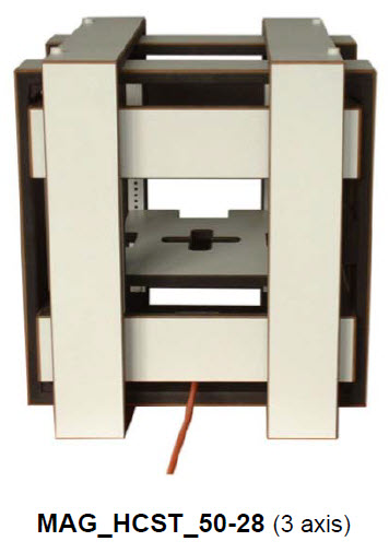
MGA_HCS_50-28
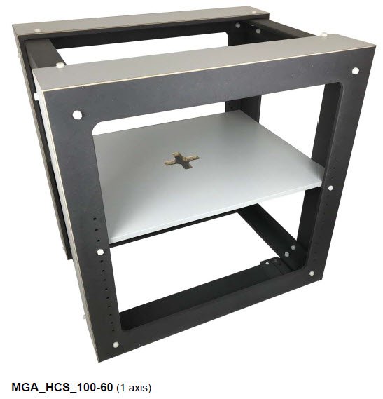
A Helmholtz coil consists of two identical wound coils, which are electrically connected in series and placed symmetrically along a common axis. The special feature is the large homogeneity of the magnetic field in the middle between the two coils.
Helmholtz coil arrangements of greater complexity can produce interference fields in different spatial axes. In the case of 3-axis Helmholtz coils, three coil pairs are arranged in the X, Y and Z directions. By means of a suitable control unit, the test specimen can thus be fully exposed to the interference field over a wide frequency range in all three spatial axes.
If the geometry is fixed, the magnitude of the magnetic field is directly proportional to the number of windings and the applied current. When designing the coils it is attempted, on one hand, to provide the highest possible number of windings in order to keep the necessary current (and thus the amplifier power) small. On the other hand, a high number of windings at higher frequencies (the MIL-STD-461E requires, for example, tests up to 100 kHz) leads to large coil impedances which, in turn, result in impractically high amplifier output voltages.
Since the required field strength decreases with increasing frequency (for the MIL-STD-461E mentioned above, the required test level at 100 kHz falls to less than one thousandth of the output value at 60 Hz), the ideal solution is the construction of a Helmholtz coil with two separate windings as in the MGA_HCS Helmholtz coils.
The basic design is shown in the following figure:
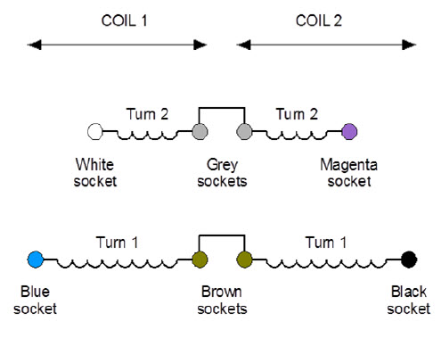
If the output of a power amplifier is connected to the «blue» and «black» jacks, a Helmholtz coil with a high coil factor is available, ideal for generating high field strengths at low frequencies where the coil inductance is not yet important. If the output of a power amplifier is connected to the «white» and «magenta» jacks, a low inductance Helmholtz coil is available, ideal for generating medium field strengths at higher frequencies.
General structure of MGA_HCS Helmholtz coils
The Helmholtz coils of the MGA_HCS series are completely made of wood materials. There are no metallic parts other than wire and connectors. The coils are completely clad with a durable laminate – the wire is not visible and thus protected against damage.
| Type |
Helmholtz coil |
Helmholtz coil |
| Number of axis |
1 |
1 |
| Frame lenght [cm] |
50 |
100 |
| Number of turns (each coil) |
26 + 4 |
44 + 10 |
| Distance between coils [cm] |
28 |
60 |
| Coil factor [m-1] (typical) |
65.9 / 11.2 |
62.1/ 13.4 |
| DC Resistance [Ω] (typical) |
0.63 / 0.15 |
2.27 / 0.43 |
| Inductivity [mH] (typical) |
1.73 / 0.07 |
15.8 / 0.65 |
| Resonant frequency [kHz] |
>700 |
>150 |
| Continuous current / short- time current [A] |
16 / 20 |
16 / 20 |
| Type |
Helmholtz coil |
Helmholtz coil |
| Number of axis |
1 |
3 |
| Frame lenght [cm] |
125 |
50 / 46 / 42 |
| Number of turns (each coil) |
50 + 10 |
26 + 4 |
| Distance between coils [cm] |
75 |
28 |
| Coil factor [m-1] (typical) |
47.5 / 10.3 |
X-Axe: 66.1 / 11.3 |
| DC Resistance [Ω] (typical) |
9.8 / 2.0 |
X-Axe: 0.58 / 0.10 |
| Inductivity [mH] (typical) |
16.4 / 1.0 |
X-Axe: 1.73 / 0.07 |
| Resonant frequency [kHz] |
>150 |
>700 |
| Continuous current / short- time current [A] |
5 / 7 |
16 / 20 |
CLICK HERE FOR A LARGER VERSION OF
THE SPECIFICATIONS MATRIX
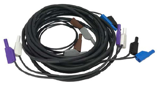
The scope of supply of the Helmholtz coils includes a cable set (3m length) which is designed for maximum current.
![]() Schlöder Helmhotz Coils MGA_HCS_125-75 MGA_HCS_100-60 MGA_HCS_50-28 MGA_HCST_50-28 Data Sheet
Schlöder Helmhotz Coils MGA_HCS_125-75 MGA_HCS_100-60 MGA_HCS_50-28 MGA_HCST_50-28 Data Sheet