
KAPTEOS PRODUCT LINE
The Value and Benefits of Electro-optic Technology
Kapteos Products
• eoSense™ Optic to Electro Converter
• eoProbe™ to measure E-field (EMF)
•• eoCal™ – eoProbe Calibration
•• eoLink™ – 100m Fiber optic extension
•• eoPod™ – eoProbe Articulated Arm and Stand
Kapteos – On-Site Training
• Applications (Target Markets)
• Antennas – Measurement of E-fields Emitted by Antennas• NFACS (Near Field Antenna Characterization Solution)
• 3D NFACS (Near Field Antenna Characterization Solution)
• Vectorial & Characterization of Ultra Compact Antennas
• EMC -Measurement of E-Fields in Electromagnetic Compatibility
• EMP – Time-resolved measurements of Electromagnetic Pulse
• High Temperature – Measurement in High Temperature
• High Voltage – Measurement of E-fields in High Voltage
• Measuring the E-Field around a Laptop
• MRI – Measurement of E-fields inside an MRI
• Plasma – Measurement of E-fields inside Plasma
• SAR – Specific Absorption Rate (SAR) assessment
• Online Software Simulation Tool – Determine Online, before you purchase, the value of the Kapteos Solution!
• FAQ’s – A wealth of Information!
RELIANT EMC PRODUCT LINES
MANUFACTURERS
Request a Quote / Contact Us!
KAPTEOS ELECTRO-OPTIC TECHNOLOGY
ELECTRIC FIELD PROBE BASED ON ELECTRO-OPTIC TECHNOLOGY
The Kapteos eoProbe is based on the Pockels effect.
The optoelectronic eoSense converts in real-time with 100% analogue components the optic signal into a voltage which is proportional to the E-field magnitude.
![]() Application Note: E-field Measurement System Basic Technology
Application Note: E-field Measurement System Basic Technology
![]() Application Note: Comparison of different E-field measurement systems
Application Note: Comparison of different E-field measurement systems
Kapteos is proud to offer their high-end electro-optic technology (based on 15 years of research and development) to the worldwide market. This technology offers the highest possible performances to measure electric fields in almost any harsh environments. Kapteos, as an expert in terahertz and electro-optic technologies, is constantly improving their systems, accessories, services, …
Main Features of the Kapteos E-Field Measurement Solution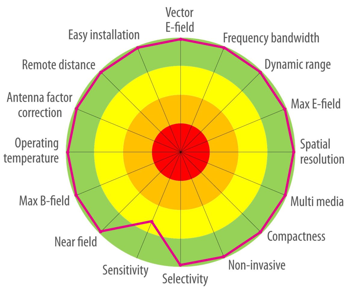
Main Features of the Kapteos E-Field Measurement Solution
• Vector E-field: 3 axis + phases
• Frequency bandwidth: 10 Hz to 100+ GHz with sub-nanosecond temporal resolution
• Dynamic range: 50 mV/m to several MV/m
• Max E-field: > 10MV/m without damage
• Spatial resolution: < 1 mm
• Multi media: Air, Liquids, Gas, Vacuum
• Compactness: 5 * 35 mm sensing probe
• Non-invasive: no metal => no impact on E-field
• Selectivity: > 50 dB Sensitivity: 50 mV/m/√Hz (air, longitudinal probe)
• Near field: down to 0 mm distance
• Max B-field: withstand more than 4.7T
• Operation temperature: 0 to 50°C (probe)
• AF correction: automatic and real-time
• Remote distance: up to 100 meters
• Easy installation: set-up ready in < 5 min
eoProbe: the probe to measure the E-field (EMF)
PRINCIPLE OF ELECTRO-OPTIC TECHNOLOGY BASED ON POCKELS EFFECT
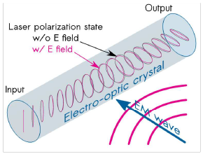
The Kapteos Electromagnetic measurement systems is composed of the eoSense Converter opto-electronic converters and the eoProbe optical probes, which are based on the Pockels effect. This latter effect occurs in some optical crystals, called electro-optic (EO) crystals, and manifests itself as an E-field induced modification of the principal dielectric axes of the EO crystal. An EO crystal behaves like a waveplate for a laser beam passing through it. Under applied E field, the dephasing induced by the waveplate is modified in proportion to the field strength. This occurs through the E-field induced variation of the refractive indices of the EO crystal. For a comprehensive description of the use of Pockels effect in E field sensors, the reader may refer to J. Opt. Soc. Am. B Vol. 19, pp 2704-2715 (2002).
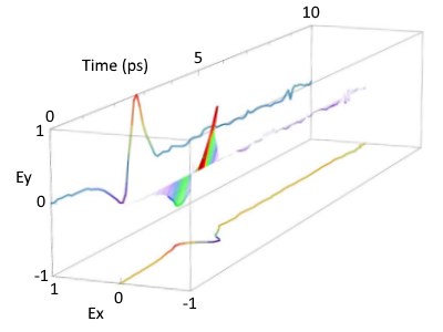
COMPREHENSIVE MEASUREMENT OF THE E-FIELD VECTOR
The electro-optic technology allows to measure the 3 components and the phase of a vector electric field. This is also the case for Kapteos probes. The 3 axis of the vector are clearly measured independently thanks to the eoSense opto-electronic converter and the longitudinal and transverse probe types. On top of that, Kapteos accessories facilitate the physical installation setup of probes to operate an easy and repetitive measurement.
NON INVASIVE MEASUREMENT
![]() The eoProbe does not include metal parts.
The eoProbe does not include metal parts.![]() The active part of the sensor is based on Crystal.
The active part of the sensor is based on Crystal.![]() The measured signal is transmitted by a laser inside a fiber optic link.
The measured signal is transmitted by a laser inside a fiber optic link.
The major advantages of this design are:
• The measured electric field is not disturb unlike the classical antenna based probes
• The probe and the opto-electronic converter may be separated up to 100 meters :
• • With extreme low losses particularly in the GHz frequencies
• • To ensure correct measured without being impacted by radiated fields
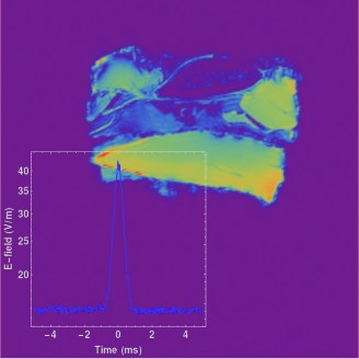
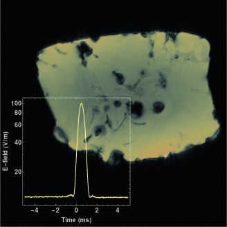
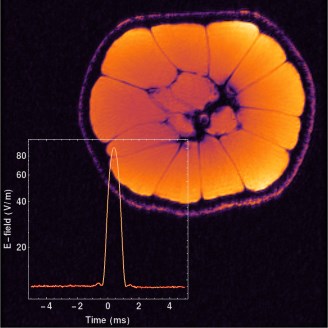
The pictures below (collaboration with Creatis) show measurements of electric fields inside animal tissues, fruits or vegetables inside an MRI system where tests have proven the non disturb imaging results.
MORE THAN 130 DB OF DYNAMIC MEASURING RANGE
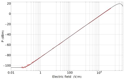
With a theoretical limit of 140 dB dynamic range, Kapteos has demonstrated with several tests the capability for the eoProbe to have a dynamic range just above 130 dB which is much more than you would need in any kind of application. The dynamic range is the ration in dB between the maximum allowed E-field divided by the minimum allowed E-field.
The technology has also proven that, over a dynamic range of 120 dB, repetitive measurements even at different moments, the absolute values stay within a tolerance better than ± 0.25 dB. Electro-optic technology is a technology you can trust.
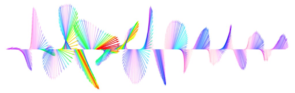
8 DECADES FREQUENCY BANDWIDTH AND ULTRA FAST RESPONSE
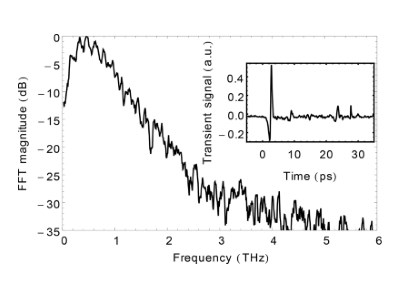
Terahertz Signal frequency domain electric field
pico second time domain electric field
It has been demonstrated via several tests and international publications that the electro-optic technology can measure electric fields up to several terahertz (THz) in either frequency domain or time domain. This is of importance when the applications requires to measure typically a very narrow single pulse like for example nano pulse generators for food sterilization or Electromagnetic Pulses (EMP) used by defense organizations. Kapteos probes can, without any difficulties, measure continuous waves or any other wave forms. Measurements performed at IMEP-LAHC lab, Université Savoie-Mont-Blanc.
INSULATED PROBE TO ENSURE SAFE MEASUREMENTS
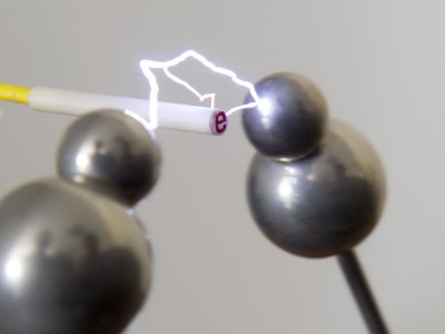
KAPTEOS eoProbe insulated Electric Field Probe
Thanks to the design based on electro-optic technology, the probe is metal-free. The measured signal is transmitted to the opto-electronic converter via a fiber optic link. These are perfect conditions to ensure a good insulation between the DUT (Device Under Test) and our probe. That’s why it is possible, in some cases, to measure the electric field at a very short distance (few millimeters) or even directly in contact with the DUT. When security matters!
SUB-MILLIMETER SPATIAL MESUREMENT RESOLUTION
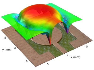
Some applications requires very precise localization of the measured field like patch antennas, specific absorption rate assessment, EMC, … The spatial resolution is the smallest distance between two steps of measurements placed next to each other. This resolution is linked to the physical dimension of the laser beam: 0.6 mm. So if the probe moves of 0.6 mm (x or y axis), a new electric field measurement can be made. Kapteos indicates a resolution of 1 mm to be valid in all cases. This spatial resolution should be more than enough for most of the applications.
MORE THAN 50 DB OF SELECTIVITY
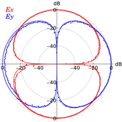
KAPTEOS Measurement showing Selectivity of EMF Probe
An essential feature related to vector E-field measurements concerns the ability of measuring a given E-field component while rejecting the orthogonal ones. Kapteos probe allows a rejection ratio of more than 50 dB (more than 99.7%) which is more than enough for most of applications. The curve shows that the position of the concerned axis must placed quite accurately to ensure this high selectivity.
This feature is of importance for transverse probe type (ET… and not EL…). To ease the probe setup, the transverse probes have an directional arrow on the side of the probe. This arrow must must be placed in accordance with the electric field orientation. See FAQs on probe for more details (How can I make sure the probe is correctly oriented in accordance with the axis of the component of the E-field to measure?).
REAL-TIME ANTENNA FACTOR CORRECTION FOR STABLE MEASUREMENTS FROM 0 TO +50ºC
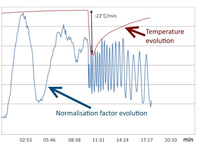
KAPTEOS Antenna Factor Correction
This high-end advanced feature allows to measure the absolute value of the electric field with an exceptional stability whatsoever the temperature variations, the hook-up losses, the duration of the measure which could be days. This compensation is performed in real-time by the eoSense opto-electronic converter. This is a compulsory feature when repetitive electric field measurements must be performed at different steps or over a long period of time. The Antenna Factor variation on the right picture lies within 1% without any correction.