
KAPTEOS PRODUCT LINE
The Value and Benefits of Electro-optic Technology
Kapteos Products
• eoSense™ Optic to Electro Converter
• eoProbe™ to measure E-field (EMF)
•• eoCal™ – eoProbe Calibration
•• eoLink™ – 100m Fiber optic extension
•• eoPod™ – eoProbe Articulated Arm and Stand
Kapteos – On-Site Training
• Applications (Target Markets)
• Antennas – Measurement of E-fields Emitted by Antennas• NFACS (Near Field Antenna Characterization Solution)
• 3D NFACS (Near Field Antenna Characterization Solution)
• Vectorial & Characterization of Ultra Compact Antennas
• EMC -Measurement of E-Fields in Electromagnetic Compatibility
• EMP – Time-resolved measurements of Electromagnetic Pulse
• High Temperature – Measurement in High Temperature
• High Voltage – Measurement of E-fields in High Voltage
• Measuring the E-Field around a Laptop
• MRI – Measurement of E-fields inside an MRI
• Plasma – Measurement of E-fields inside Plasma
• SAR – Specific Absorption Rate (SAR) assessment
• Online Software Simulation Tool – Determine Online, before you purchase, the value of the Kapteos Solution!
• FAQ’s – A wealth of Information!
RELIANT EMC PRODUCT LINES
MANUFACTURERS
Request a Quote / Contact Us!
KAPTEOS NFACS
Kapteos is targeting the following applications where their products and services would be of interest to the relevant organization.
ANTENNA – NEAR FIELD ANTENNA PATTERN CHACTERIZATION

Kapteos is now offering a comprehensive system to perform in-house antenna pattern characterization for our customers or to sell a customized system adapted to our customer’s needs.
Thanks to the electrooptic technology used in our probes, we offer a unique solution:
• E-Field measurement system
• Cartesian robot
• Vector Network Analyzer if required
• Software to obtain automatically the antenna pattern
![]() Application Note: Near Field Antenna Pattern Characterization
Application Note: Near Field Antenna Pattern Characterization
How do we operate?
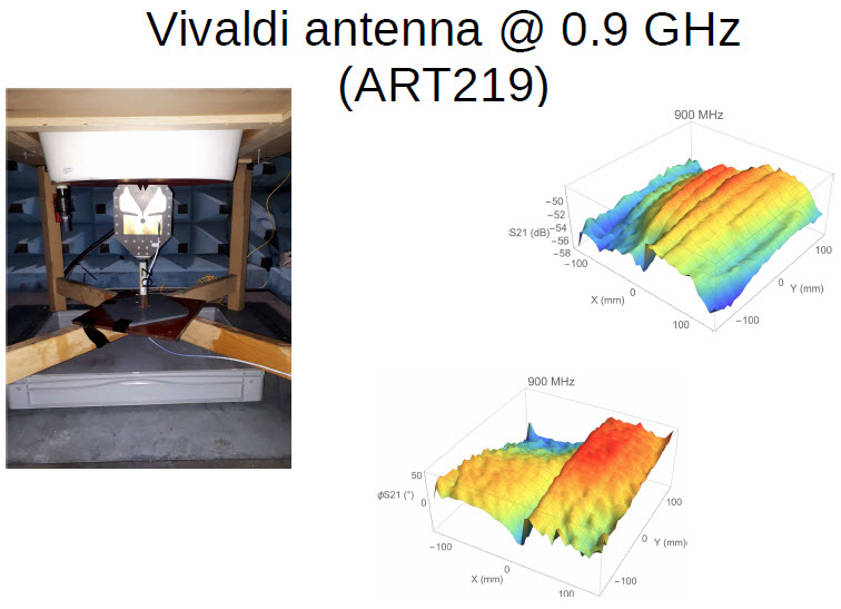
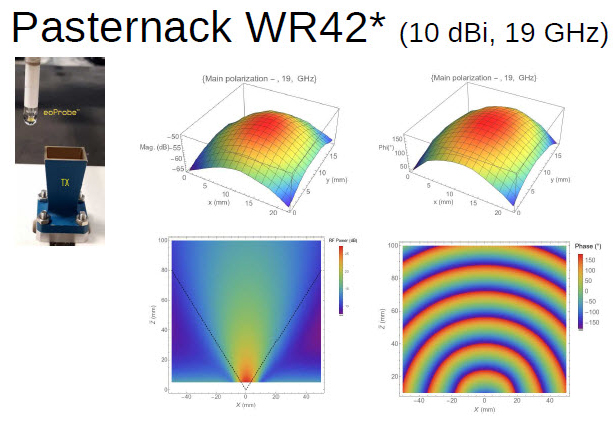
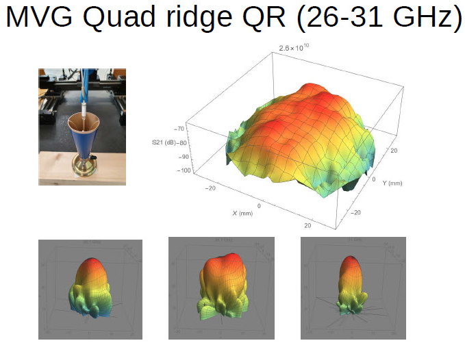
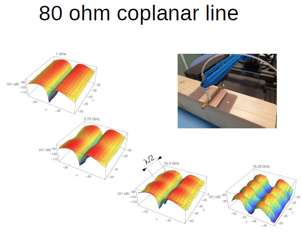
STEP 1 The probe is placed few mm away from the antenna. In practice, there is no limitation in terms of antenna size. The Cartesian robot is moving the probe on a single plane (2D E-field mapping).
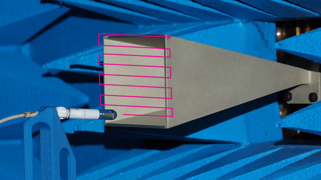 At each position, the Vector Network Analyzer measures the field strength and its phase.
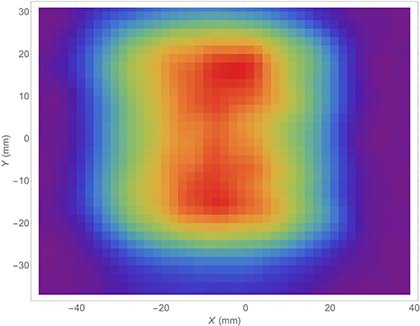 MODULUS (raw data)
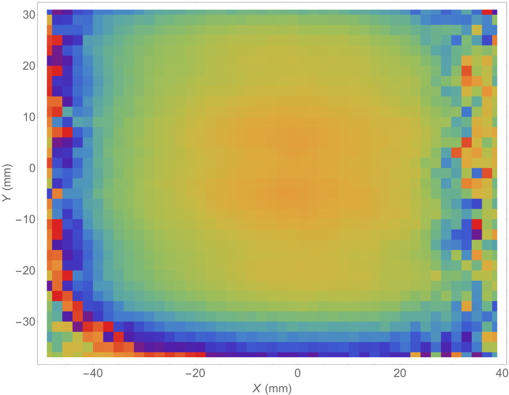 PHASE (raw data)
STEP 2
From the raw data (field strength and phase) at each position of the probe, the software operates a near to far field transformation.
In our case, there is no pre-treatment, no post-treatment, no de-embedding in order to compensate probe interference or setup artefact as our probes are full none interfering. The software operates just the near to far field transformation, no more no less!
With Kapteos you get a fully open-system with no hidden algorithms.
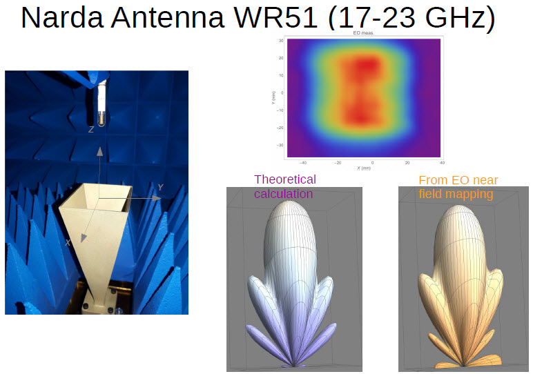
In the example below, we obtain the pattern of the Narda ATM 51-442-6 horn antenna used in the above setup.
We provide the E plane and the H plane antenna radiations.
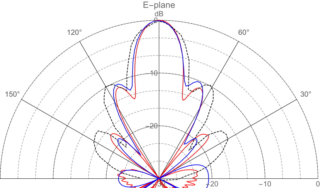
Black dotted line is the manufacturer data (typical values)
Blue solid line is the radiation pattern extracted from near field mapping
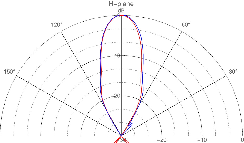
Red solid line is ElectroMagnetics simulation performed by HFSS software (in collaboration with IMEP-LAHC lab Savoie-Mt-Blanc University)
Blue solid line is the radiation pattern extracted from near field mapping
Examples:
Kapteos supports the following antennas and devices
● Spiral antenna for hyperthermia (115 MHz) in liquid phantom
● Various antennas for hyperthermia in liquid phantoms
● GTEM cell (ns pulse)
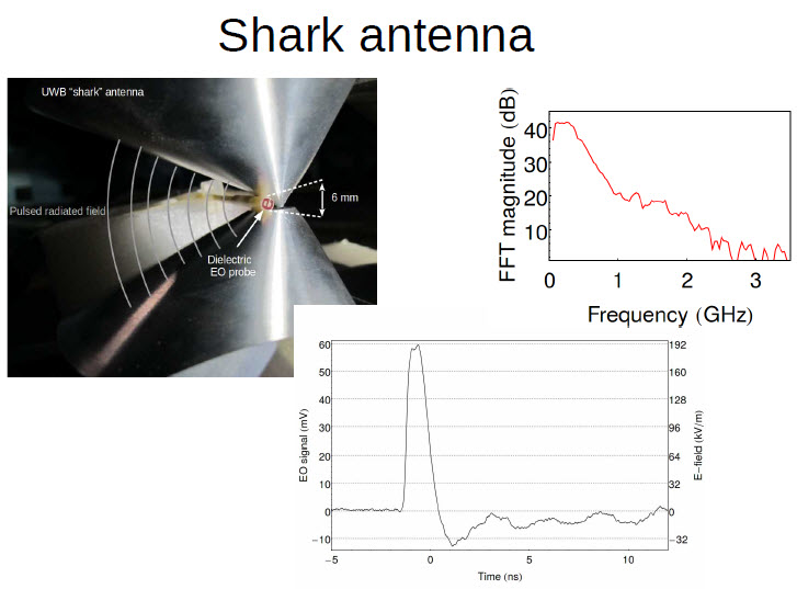
● UWB ridge antenna
● TEM cells
The system is dedicated to the customers’ needs.
However the following main specifications could be mentioned:
• From few hundreds of MHz to more than 100 GHz
• Easy operation with fast results (mapping may be less than 15 minutes)
• Comprehensive system, all included
![]() Application Note: Near Field Antenna Pattern Characterization
Application Note: Near Field Antenna Pattern Characterization