
LAPLACE INSTRUMENTS PRODUCT LINE
Products by EMC Categories
Emissions
• Antennas
• EMC Emission Analyzers
• LISN
• Near Field Probes
• Pre-selector
• Reference Sources
• RF Sensors/Probes
• Test Cells
• Test Chambers
• Voltage Probe (PLIP)
Harmonic and Flicker
• AC2000A Harmonics & Flicker Analyzer
• AC1000 Clean Power Source
Immunity
• CDN’s
• Dips and Interrupts
• EFT & Burst
• ESD
• Power Amplifiers
• Sensors/Probes
• Surge
• Synthesizers
• Test Cells
• Test Chambers
Mains Filters
Product Software
RF Meters and Sensors
Systems
• Conducted Emissions
• Conducted RF immunity IEC1000-4-6
• Harmonic and Flicker
• Luminaire Test (EN55015)
• Non-RF Immunity IEC61000-4-4 IEC61000-4-5 IEC61000-4-11
• RF Emissions (CDN)
• RF Emissions (Cell/Chamber)
• RF Emissions (OATS)
• RF Immunity (Cell/Chamber) IEC61000-4-3
• Standards
• Sale! Radiated Emission Test System – Reduced!
RELIANT EMC PRODUCT LINES
MANUFACTURERS
Request a Quote / Contact Us!
LAPLACE INSTRUMENTS RF EMISSIONS (CELL/ CHAMBER) SOLUTION
Typical arrangement for emissions measurement in LC300/2
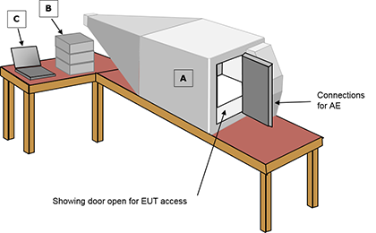
Equipment required:
A LC300/2 Test cell
B SA1002 EMC analyzer
C EMCEngineer Software for your PC
Note:
For a 3GHz system, change the EMC analyzer to a SA3000.
The LC300 accepts products up to 30 x 30 x 30cm.
Filters for I/O feeds to the EUT can be fitted to suit customer requirements (e.g., USB, Ethernet, Power, RS232, RF feeds, etc…)
LC600
Typical arrangement for emissions measurement in LC600
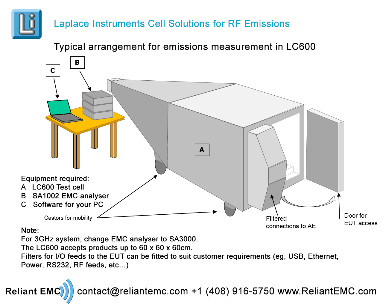
Equipment required:
A LC600 Test cell
B SA1002 EMC analyzer
C EMCEngineer Software for your PC
Note:
For a 3GHz system, change the EMC analyzer to a SA3000.
The LC300 accepts products up to 30 x 30 x 30cm.
Filters for I/O feeds to the EUT can be fitted to suit customer requirements (e.g., USB, Ethernet, Power, RS232, RF feeds, etc…)
CHAMBER EMISSION MEASUREMENT SYSTEM
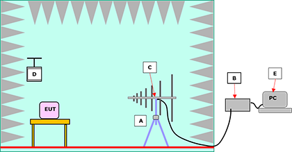
Equipment required:
A RF200 Antenna + stand
B SA1002 EMC analyzer
C SA1020 pre-amplifier
D ERS Reference source
E EMCEngineer Software for your PC
Note:
For a 3GHz system solution, add the RF230 Antenna and change the EMC analyzer to a SA3000
Practical notes:
Ambient noise will be essentially eliminated. However, chamber characteristics may introduce uncertainties which can be corrected by use of the ERS. Diagram shows SAC (Semi Anechoic Chamber) with reflective floor to emulate OATS. FAC (Fully Anechoic Chamber) has RF absorber on the floor. This avoids the requirement for height scanning of the antenna.