
KAPTEOS PRODUCT LINE
The Value and Benefits of Electro-optic Technology
Kapteos Products
• eoSense™ Optic to Electro Converter
• eoProbe™ to measure E-field (EMF)
•• eoCal™ – eoProbe Calibration
•• eoLink™ – 100m Fiber optic extension
•• eoPod™ – eoProbe Articulated Arm and Stand
Kapteos – On-Site Training
• Applications (Target Markets)
• Antennas – Measurement of E-fields Emitted by Antennas• NFACS (Near Field Antenna Characterization Solution)
• 3D NFACS (Near Field Antenna Characterization Solution)
• Vectorial & Characterization of Ultra Compact Antennas
• EMC -Measurement of E-Fields in Electromagnetic Compatibility
• EMP – Time-resolved measurements of Electromagnetic Pulse
• High Temperature – Measurement in High Temperature
• High Voltage – Measurement of E-fields in High Voltage
• Measuring the E-Field around a Laptop
• MRI – Measurement of E-fields inside an MRI
• Plasma – Measurement of E-fields inside Plasma
• SAR – Specific Absorption Rate (SAR) assessment
• Online Software Simulation Tool – Determine Online, before you purchase, the value of the Kapteos Solution!
• FAQ’s – A wealth of Information!
RELIANT EMC PRODUCT LINES
MANUFACTURERS
Request a Quote / Contact Us!
KAPTEOS 3D NFACS
ANTENNAS – 3D NFACS (NEAR FIELD ANTENNA CHARACTERIZATION SOLUTION)
Subject: NFACS – Near Field Antenna Characterization Solution
Far Field Radiation Patterns from Near Field (NF) mapping of Antennas
Objective:
1. Measurement of Near (and Far field) radiation patterns from Near Field (NF) mapping of a large variety of antennas or arrays of antennas.
2. How to characterize a wide variety of antennas from ~ 1 GHz to 20 GHz. The antennas can be a variety of antennas such as Patch, Horns, Cylindrical, Arrays, etc.
3. Frequency Range: 100 MHz – 20 GHz. The power that will be injected to the AUT (Antenna Under Test) is typically 1W.
4. The antenna will be housed in a 400 mm diameter sphere. Therefore the maximum size of the antenna can be no greater than the internal dimensions of the 400 mm diameter sphere.
5. The proposed solution shall be comprehensive with near to far field transformation includes everything needed with the exception of an embedded VNA (Vector Network Analyzer), which must be provided by the testing site.
6. A unique feature of this solution is its ability to measure extremely close to, or WITHIN the E-Field Source.
Solution offered by Kapteos
The proposed NFACS (Near Field Antenna Characterization Solution) solution is composed of:
A – A versatile and universal 7-axis (based on a Stäubli TX2 40 6-axis industrial robot) scanning system (RF absorber covered) with a non-interfering removable probe holder
B – A heavy table with a 100 mm diameter hole for the RF power supply of the AUT
C – A removable anechoic base plate covered with pyramidal absorbers
D – A magnetic kinematic antenna holder with a holding force of 40N
E – A duo channel/band optoelectronic converter Kapteos eoSense HF20-2-SP-XXX with 2 RF bands (100 MHz – 12 GHz & 12-20 GHz) covering the whole frequency range from 100 MHz up to 20 GHz
F – A high sensitivity transverse Kapteos E-field probe eoProbe ET5-air for the first band 100 MHz – 12 GHz and a high speed transverse E-field probe ET1-air for the second band 12GHz–20GHz
G – A removable wheeled anechoic tunnel
H – An instrumentation software controlling the 7-axis scanning system, the eoSense optoelectronic converter and the end customer vector network analyzer
I – a near to far-field transformation software working in different possible coordinates geometries (Cartesian, cylindrical, spherical and conformable in the future)
Option J – some specific holders with a touch-trigger probe for an automatic mechanical calibration of the NFACS and the implementation of the calibration procedure in the software (part H)
The maximum volume of measurement is a sphere of 500 mm in diameter.
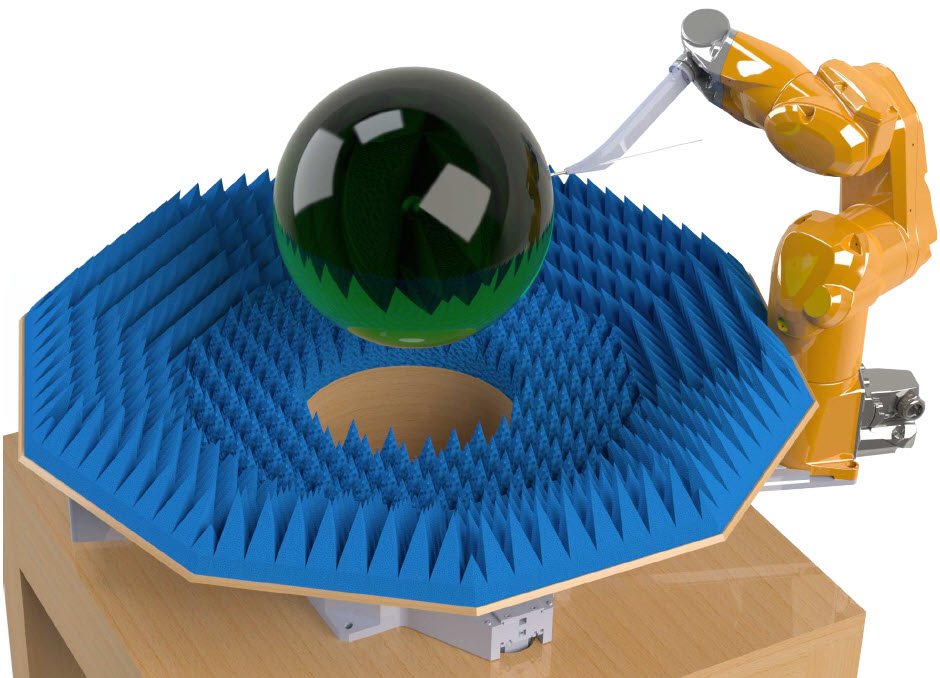
Two artist views of the solution are given hereafter.
Artist overview of the Near Field Antenna Characterization Solution (NFAC)
- Removable anechoic base plate is covered with (blue) RF pyramidal absorbers
- 6-axis robot (yellow) is shown without its silicon RF absorber cover
- Heavy table with large motorized stage below the base plate
- Sphere from the surface of which the E field mapping is carried out (dark green)
- Not Included: Antenna holder and removable wheeled anechoic tunnel
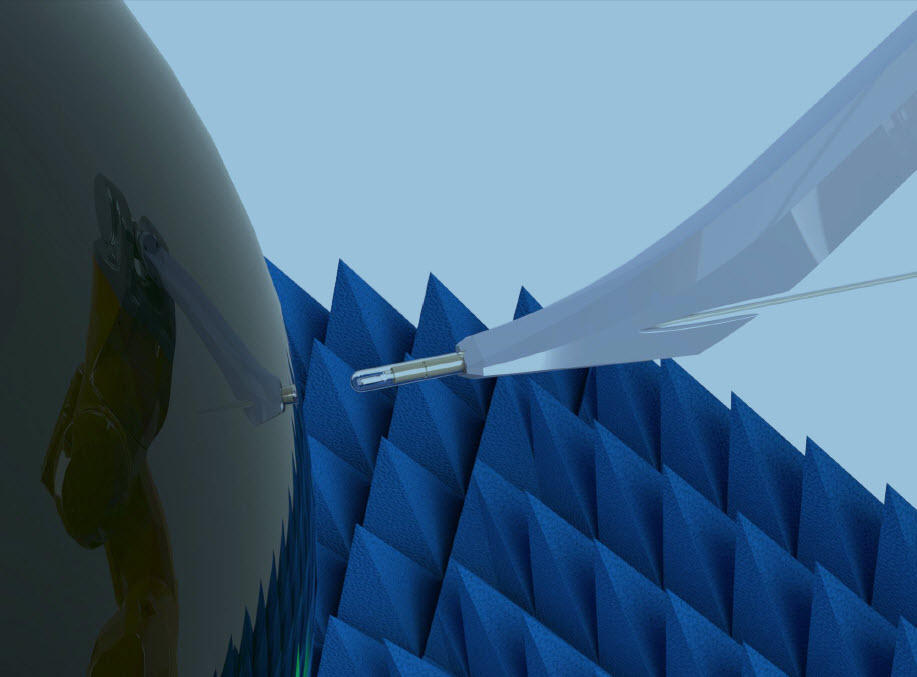
Artist detailed view of the non-interfering optical E-field probe at the surface of the spherical measurement surface with its non-interfering faceted holder (low permittivity and ultra high loss tangent)
Specifications of the comprehensive NFACS
The specifications of the comprehensive NFACS are detailed below for each of its main components A to J.
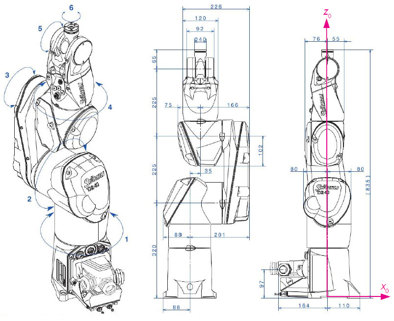
A. Specifications of the versatile and universal 7-axis scanning system (RF absorber covered) with a non-interfering removable probe holder
The 7-axis scanning system is based on a 6-axis industrial robot (Stäubli TX2 40) with repeatability (ISO 9283) of ± 20 µm (relative positioning). Due to dispersion of the robot Denavit-Hartenberg parameters, absolute positioning errors ~ 2 mm with respect to a referential point could be achieved without calibration of the robot (cf. PhD thesis “Identification et simulation physique d’un robot Stäubli TX90 pour le fraisage à grande vitesse”, Hiba Hage, 2012). With robot calibration, absolute errors are reduced by a 10 factor to 200 µm (i. e. less than λ/75 @ 20 GHz). The 7-axis is linked to a heavy/75 @ 20 GHz). The 7-axis is linked to a heavy load rotary table (up to 150 kg) with a large aperture > 300 mm.
Specifications of the 7-axis Scanning System
|
|
1 |
2 |
3 |
4 |
5 |
6 |
7 |
|
Motion range |
±180° |
±125° |
±138° |
±270° |
+133.5° |
±270° |
360° |
|
Maximum speed (°/s) |
555 |
475 |
585 |
1035 |
1135 |
1575 |
318 |
|
Encoder resolution |
> 16 bits |
20000 points/turn |
|||||
|
Angular resolution |
1 arc minute |
~ 1 arc minute |
|||||
|
Repeatability |
± 20 µm (ISO 9283) on x, y & z (see picture above) |
4 arc minutes |
|||||
|
Absolute positioning |
~ 2 mm for the position x, y & z: A/7.5 @ 20 GHz |
|
|||||
|
versus referential point |
~ 0.3° for Euler spherical angles defining the E-field |
4 arc minutes |
|||||
|
without calibration |
probe orientation |
|
|||||
|
Absolute positioning |
200 µm for the position x, y & z: |
A/75 @ 20 GHz |
|
||||
|
versus referential point |
~ 0.3° for Euler spherical angles defining the E-field |
4 arc minutes |
|||||
|
with calibration |
probe orientation |
|
|||||
|
Overall robot height |
1005 ± 5 mm for resting position |
||||||
The 6-axis robot will be covered by a removable silicon-based cover RF absorber. The weight of the 7-axis scanning system is between 60 and 70 kg, taking into account the robot counterweight for bringing the center of gravity of the scanning system in the aperture of the rotary table.
The probe holder is a removable magnetic probe holder based on 3 hardened balls, each of them being in contact with 2 dowel pins for a perfect repositioning of the probe. The probe holder is maintained in position via a rare earth magnet with a holding force of 30 N. A dummy probe permits to experimentally simulate the near-field antenna characterization at high speed. A lever tool is provided for an easy removal of the probe holder from the 6-axis robot.
The main specifications concerning this removable probe holder are given hereafter.
| Repositioning accuracy in position |
Repositioning |
Holding |
Holder |
Holder |
Overall |
Holder |
|
≤ 50 µm in |
≤ 50 µrad for |
~ 30 N |
40 mm |
165 mm |
≤ 175mm |
HDPE, PEEK and/or TPX + glass fiber reinforced epoxy |
B. Specifications of the heavy table with a 100 mm diameter hole for the RF power supply of the AUT
The wood-based heavy table supporting the 7-axis scanning system (part A), the removable anechoic base plate (part C) and the magnetic kinematic antenna holder (part C). The overall weight supported by the table is between 70 and 90 kg. Its characteristics are given in the following table.
|
Width |
Depth |
Height |
Table top thickness |
Hole diameter for RF cable feed-through |
|
1 m |
1 m |
0m70 |
> 40 mm |
≥ 100 mm at table center |
C. Specifications of removable anechoic base plate covered with pyramidal absorbers
The anechoic base plate placed in the aperture of the rotary table is composed of:
- a cylinder mechanically adjusted to the aperture of the rotary table with an inner diameter of 340 mm and an outer diameter of 360 mm, the base of the cylinder embedding the support for the magnetic kinematic antenna holder
- a horizontal dielectric-based 10-sided polygon with sides having a length of 230 mm, covered by pyramidal absorbers (upper side of the wood-based polygon ~ 80-85 mm above the heavy table)
- 10 wood-based panels making an angle of 30° with respect to the horizontal wood-based, each one being covered by pyramidal absorbers.
The removable anechoic base plate is placed on the rotary table of the 7-axis scanning system and securely and very precisely positioned and oriented via locating pins and 3 ceramic disks.
D. Specifications of magnetic kinematic antenna holder with a holding force of 40 N
The antenna holder is based on 3 hardened balls (∅ 3/8”) in contact with 2 dowel pins (∅ 3/16” – 3/8”) in contact with 2 dowel pins (∅ 3/8”) in contact with 2 dowel pins (∅ 3/16” – 3/16” – length 5/8”) with rare earth magnets that ensure a magnetic locking of the antenna holder with a holding force of 40 N. A lever tool is provided for an easy removal of the antenna holder.
Magnetic Kinematic Antenna Holder Specifications
Repositioning
|
Repositioning |
Holding force |
Holder |
Hole diameter |
Overall |
Nominal AUT |
|
≤ 50 µm in |
≤ 50 µrad for |
≥ 40N |
300 mm |
100 mm |
600 mm |
650 mm |
The nominal “center of gravity” of the AUT should be located 650 mm over the removable anechoic base plate (part C) whereas the holder height is 600 mm. This means that the specific AUT adapter for the magnetic kinematic antenna holder should present a thickness of 50 mm for a mapping in spherical coordinates. In case of a Cartesian mapping for a horn, this consideration does not apply. On request other magnetic kinematic antenna holder could be manufactured with different overall height in order to adapt to very specific antennas.
E. Specifications of the duo channel/band optoelectronic converter eoSense HF20-2-SP-XXX with 2 RF bands (100 MHz – 12 GHz & 12-20 GHz) covering the whole frequency range from 100 MHz up to 20 GHz
The optoelectronic converter for the E-field probes presents 2 channels with their own frequency range, the first one being dedicated for the high sensitivity transverse E-field probe ET5-air whereas the second one is being dedicated for the high speed E-field probe ET1-air.
The guaranteed performances of the optoelectronic converter eoSense HF20-2-SP-XXX associated with the probes eoProbe ET5-air and ET1-air are given in the Table hereafter.
|
Couple probe-converter |
Configuration ①: ET5-air probe: ET5-air probe |
Configuration②: ET1-air probe: ET1-air probe |
|
Min. measurable E field in frequency domain defined as noise power = signal power1 |
< 250 mV/m. v’Hz |
< 1 V/m. v’Hz |
|
Saturation E field2 |
> 800 kV/m |
> 3.2 MV/m |
|
E field damage threshold3 |
> 10 MV/m |
> 10 MV/m |
|
Max. antenna factor4 |
< 130 dB/m |
< 145 dB/m |
1 The minimum measurable E field is given for direct connection of the probe eoProbe to the optoelectronic converter eoSense.
2 The saturation E field strength is the rms value of the field for which a deviation of 3 dB from the system linear response occurs.
3 When E field strength is much higher than the saturation E field, measurements can still be done. A post-treatment (probe non-linear response de-embedding) can be carried out in order to get a temporal signal free of non-linearity effects. Kapteos experts could help the customer if such situation occurs.
4 The formula giving the output power delivered by the optoelectronic converter as a function of the antenna factor AF and the E field strength E is:
PeoSense [dBm] = E [dBVrms /m] – AF [dB/m] + 13.010
As a consequence of this formula and the above mentioned minimum measurable E-field, it is important to get E field strengths generated by the AUT of at least 10 V/m, and preferably of ~ 100 V/m. For near-field measurement, the table below gives the correspondence between the power densities (easily calculable as the injected RF power divided by the radiating surface of the antenna in cm2, i.e. the injected RF power divided by the horn aperture in cm2 in case of a horn antenna).
The table gives also the signal-to-noise ratio SNR corresponding to the recommended resolution bandwidth RBW.
Power density (W/cm2) |
10-5 |
3 10-5 |
10-4 |
3 10-4 |
0.001 |
0.003 |
0.01 |
0.03 |
0.1 |
0.3 |
1 |
|
Average E-field strength (Vrms/ m) |
6.1 |
10.6 |
19.4 |
33.6 |
61.4 |
106 |
194 |
336 |
614 |
1060 |
1940 |
|
Recommended RBW (Hz) for config. ① |
1 |
1 |
1 |
1 |
3 |
10 |
30 |
100 |
300 |
1000 |
3000 |
|
SNR min. (dB) config. ① |
28 |
33 |
38 |
43 |
43 |
43 |
43 |
43 |
43 |
43 |
43 |
|
Recommended RBW (Hz) for config. ② |
1 |
1 |
1 |
1 |
1 |
1 |
3 |
10 |
30 |
100 |
300 |
|
SNR min. (dB) config. ② |
16 |
21 |
26 |
31 |
36 |
41 |
41 |
41 |
41 |
41 |
41 |
For the configuration ①, as soon as the power density exceeds 300 µW/cm2, the setup is optimal in order to get radiation pattern with high precision.
For configuration ②, the same situation occurs for power density over 3 mW/cm2.
Considering an injected power of 30 dBm, configuration
①: ET5-air probe will lead to excellent results for antenna radiating surfaces lower than 3000 cm2.
For configuration ②, this will be the case for antenna radiating surfaces lower than 300 cm
Specifications of the high sensitivity transverse E-field probe ET5-air for the first band 100 MHz – 12 GHz and of the high speed transverse E-field probe ET1-air for the second band 12 GHz – 20 GHz
Refer to eoProbe data sheet (“FT19-eoProbe-10 LoRes.pdf” joined to the present quotation) and to the above specifications table for the guaranteed performances of the couple probe-converte
Specifications of the removable wheeled anechoic tunnel.
In order to limit RF wave reflections by the room walls and ceiling, a removable wheeled anechoic chamber shall be placed over the 7-axis scanning system during the characterization.
Removable Wheeled Anechoic Tunnel specification Table
|
Width |
Depth |
Height |
RF absorber |
RF absorber |
|
~ 1m50 |
~ 2m |
~ 1m90 |
Tunnel structured internally |
Silicon based RF absorber coated |
H. Specifications of the instrumentation software controlling the 7-axis scanning system, the optoelectronic converter and the end customer vector network analyzer.
The specifications of the instrumentation controlling software are given in the Table below.
|
Instrument |
Features |
HMI |
|
|
End customer VNA |
Full control of VNA |
User control of fmin (min. frequency) fmax (max. frequency) # of frequency points IF (automatic or manual) |
|
|
7-axis scanning system |
Cartesian coordinates mode automatic calculation of δx = δy x = δx = δy y from fmax |
User control of scanning surface xmin (min. x value) xmax (max. x value) ymin (min. y value) ymax (max. y value) zsurface (vertical position of scanning surface) |
Real-time visualization of the near-field during scanning. Visualization parameters: |
|
cylindrical coordinates mode automatic calculation of δx = δy θ, φ & ψ and δx = δy z from fmax automatic blank scan (without probe) |
User control of scanning surface zmin (min. z value) zmax (max. z value) θ, φ & ψmin (min. θ, φ & ψ value – 0° by default) θ, φ & ψmax (max. θ, φ & ψ value – 360° by default) ρsurface (radial position of scanning cylindrical surface) |
||
|
spherical coordinates mode automatic calculation of δx = δy θ, φ & ψ and δx = δy φ & ψ from fmax automatic blank scan (without probe) at high speed to check the validity |
User control of scanning surface θ, φ & ψmin (min. θ, φ & ψ value – 0° by default) θ, φ & ψmax (max. θ, φ & ψ value) φ & ψmin (min. φ & ψ value – 0° by default) φ & ψmax (max. φ & ψ value – 360° by default) ρsurface (radial position of scanning spherical surface) |
||
|
Opto- electronic converter eoSense |
Full control of optoelectronic converter Automatic record of probe IL (insertion loss) for each spatial point |
User transparent |
|
|
/ |
Software output |
Set of time-referenced S21 files for each scanning point with a summary file containing the general measurement parameters and columns with: position of the scanning point insertion loss of the probe name of the S21 record |
|
I. Specifications of the near to far-field transformation software working in different possible coordinates geometries (Cartesian, cylindrical, spherical and conformable in the future).
The near to far-field transformation software will use the summary file as input for the near to far-field transformation and gives as output the far-field radiation patterns in the E plane and in the H plane:
- in high resolution images (png format)
- in set of data (csv format) for both E & H planes as the relative gain versus angle.
Option J. Specifications of the specific holders with a touch-trigger probe for an automatic mechanical calibration of the NFACS and the implementation of the calibration procedure in the software
A third probe holder (cf. part A) embedding a touch-trigger probe and a second magnetic kinematic holder (cf. part D) are used for the robot mechanical calibration. With these two specific holders and the touch-trigger probe, absolute referencing of the 7-axis scanning system will be achieved with the specifications given in the Table linked to part A.
Concerning the probe holder, the probe is replaced by a touch-trigger probe with sub-10µm spatial resolution in all directions. For the precise absolute referencing of the 7-axis scanning, the second magnetic kinematic holder embeds a 25mm edge length cube centered at the nominal position (axis of rotary table and 650 mm height with respect to the removable anechoic base plate) that will be touch-triggered on all its faces by the touch-trigger probe for a precise absolute referencing. A specific mechanical calibration procedure is added in the main software controlling the NFACS.
Specifications on accuracy for S21 parameter and far field radiation patterns
These specifications are given versus the experimental SNR (see Table on top of page7).
| SNR |
σ on modulus of S21 |
σ on phase |
|
15 dB |
1.2 dB |
10° |
|
20 dB |
0.8 dB |
6° |
|
25 dB |
0.5 dB |
3.5° |
|
30 dB |
0.4 dB |
2° |
|
35 dB |
0.3 dB |
1° |
|
40 dB |
0.25 dB |
0.6° |
|
45 dB |
0.25 dB |
0.4° |
The following curves give the accuracy with which the relative magnitude of a side lobe will be determined for different values of the antenna FAHP (Full Angle at Half Power). The radiation pattern associated to the given accuracy is given on the left with one thick contour every 10 dB.
Case of ultra low directivity antenna (FAHP = 57.4°)
.jpg)
Case of low directivity antenna (FAHP = 22.8°) .jpg)
Case of moderate directivity antenna (FAHP = 13.8°)
.jpg)
Case of high directivity antenna (FAHP = 6.8°)
.jpg)
As seen, the more directive the antenna is, the more precise is the determination of the radiation pattern. With a SNR of 40 dB and an antenna with a FAHP of 6.8°, an uncertainty better than 0.2 dB is obtained on any side lobe with a relative magnitude higher than -25 dB. This uncertainty is lower than 0.1 dB for side lobe with a relative magnitude higher than -20 dB. As seen on Table page 7, NR higher than 40 dB can be easily achieved with low to moderate near field power density. With an output of a few W, keeping low values for RBW, SNR higher than 50 dB can be easily obtained leading to radiation pattern comparable to the ones obtained in far field in costly anechoic chamber.
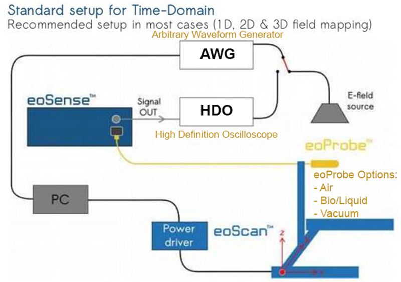
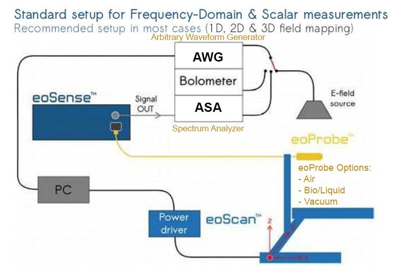
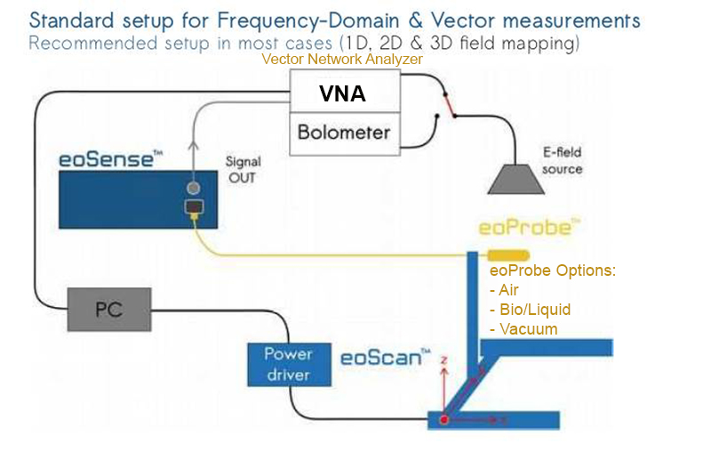
The eoSense Converter converts the optical signals transmitted by 1, 2 or 3 eoProbes into an electrical signal that can be analyzed with an instrument like an oscilloscope, a spectrum analyzer or any other signal processing instrument.
The Kapteos eoProbe measures one component of the electric field vector based on the electro-optic technology. This Ultra-Wide Band sensor allows accurate measurements in almost any location and environment (air, liquids, gases, vacuum) under harsh conditions. Each eoProbe is delivered with a Routine Test report valid for 2 years. This probe must be used with the eoSense converter.
![]() Application Note: 3D Far Field Radiation Patterns from Near Field Mapping of Antennas
Application Note: 3D Far Field Radiation Patterns from Near Field Mapping of Antennas