
KAPTEOS PRODUCT LINE
The Value and Benefits of Electro-optic Technology
Kapteos Products
• eoSense™ Optic to Electro Converter
• eoProbe™ to measure E-field (EMF)
•• eoCal™ – eoProbe Calibration
•• eoLink™ – 100m Fiber optic extension
•• eoPod™ – eoProbe Articulated Arm and Stand
Kapteos – On-Site Training
• Applications (Target Markets)
• Antennas – Measurement of E-fields Emitted by Antennas• NFACS (Near Field Antenna Characterization Solution)
• 3D NFACS (Near Field Antenna Characterization Solution)
• Vectorial & Characterization of Ultra Compact Antennas
• EMC -Measurement of E-Fields in Electromagnetic Compatibility
• EMP – Time-resolved measurements of Electromagnetic Pulse
• High Temperature – Measurement in High Temperature
• High Voltage – Measurement of E-fields in High Voltage
• Measuring the E-Field around a Laptop
• MRI – Measurement of E-fields inside an MRI
• Plasma – Measurement of E-fields inside Plasma
• SAR – Specific Absorption Rate (SAR) assessment
• Online Software Simulation Tool – Determine Online, before you purchase, the value of the Kapteos Solution!
• FAQ’s – A wealth of Information!
RELIANT EMC PRODUCT LINES
MANUFACTURERS
Request a Quote / Contact Us!
KAPTEOS E-FIELD MEASUREMENT IN HIGH TEMPERATURE
MEASUREMENT OF E-FIELDS IN A HIGH TEMPERATURE ENVIRONMENTAL
Objective:
To measure absolute E-field (its 3 components) in a harsh environment:
- • Boiler with steam at 100°C under 1 atmosphere
- • Remote measurement in a shelter ~ 30m from the boiler with link between data acquisition system and boiler feed-through being in outdoor conditions
• The measurements are carried out in the time-domain with a Tektronix oscilloscope DPO3014 (4 channels, 8 bits, 2.5 GS/s, 1mV/div for the highest sensitivity)
• The signal to be currently measured is a CW electromagnetic wave @ 6,78 MHz with a field strength ranging from 100 V/m up to 200 kV/m
• In the future, other frequencies from 200 kHz up to 7 MHz may be included to the solution
Offered solution
The following customized solution covers the E field strength and frequency range as specified above, while operating in the harsh environment of a boiler.
This customized solution is based on:
- • Two high sensitivity eoProbe ET5-vac-SP10 E-field probes dedicated to vacuum or high pressure environments with an embedded vacuum KF16 flange feed-through located 5m from the probe tip.
• The length of the probe fiber link is 10m. - • One high speed eoProbe EL1-vac-SP10 E-field probe dedicated to vacuum or high pressure environment with an embedded vacuum KF16 flange feed-through located 5m from the probe tip.
• The length of the probe fiber link is 10m. - • One three channels optoelectronic converter eoSense LF-3-SP-L3HA covering 100 kHz – 10 MHz frequency bandwidth with a software selectable gain (0 or 30 dB extra gain) on each channel (this means that the extra gain can be set on channel 2 only whereas it is not set on channels 1 and 3)
- • One customized water-cooled PEEK-Alumina composite probe holder for the three aforementioned E-field probes. The HLD-vac-Cooler is described below.
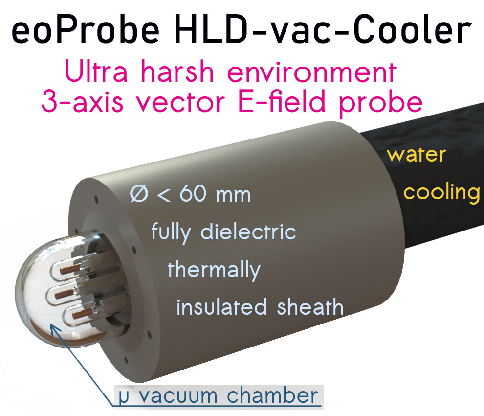
eoProbe HLD-vac-Cooler
The HLD-vac-Cooler consists of:
• Sheath made of transparent PEEK
• Dome (with a vacuum) at the end of the Sheath
• Probe Holder
• Two tubes/pipes for water
• One tube/pipe for the vacuum
The water-cooled PEEK-Alumina composite probe holder is shown (non-binding image of the holder for illustration of the principle – the final device could be slightly different) below.
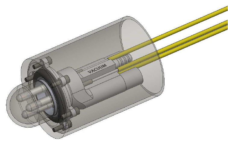
Kapteos HLD-vac-Cooler
The three E-field probes are seen on the lower left corner of the image.
The transparent element covering the whole device is the protective sheath. The protective sheath, designed to protect the three E-field probes against the high heat of the boiler, is made of PEEK (Polyether Ether Ketone). The PEEK sheath provides great resistance to heat, low permittivity, very low RF loss tangent, low heat conductivity and heat capacitance and low wettability (contact angle of 71° on raw material without any treatment). The PEEK sheath provides perfect chemical and physical compatibility with hot steam.
Between the PEEK sheath and the alumina probe holder, there is an O-ring seal (in black) to insure a rough vacuum between the three E-field probes and the PEEK dome in order to eliminate heat conduction between the PEEK protective sheath and the probes.
While the sheath will reach 100°C, the probes will be kept below 50°C due to water cooling and the vacuum created in the PEEK dome. The water will enter and exit the alumina probe holder via two water pipes displayed in the image above.
The water pipes can be seen at the top rear of the alumina probe holder to the “Left” and “Right” of the inscription “vacuum”. The vacuum pipe is located above the water pipes.
The probe holder is made of alumina for its outstanding strength, ultra low loss tangent and excellent heat conduction.
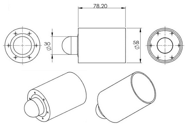
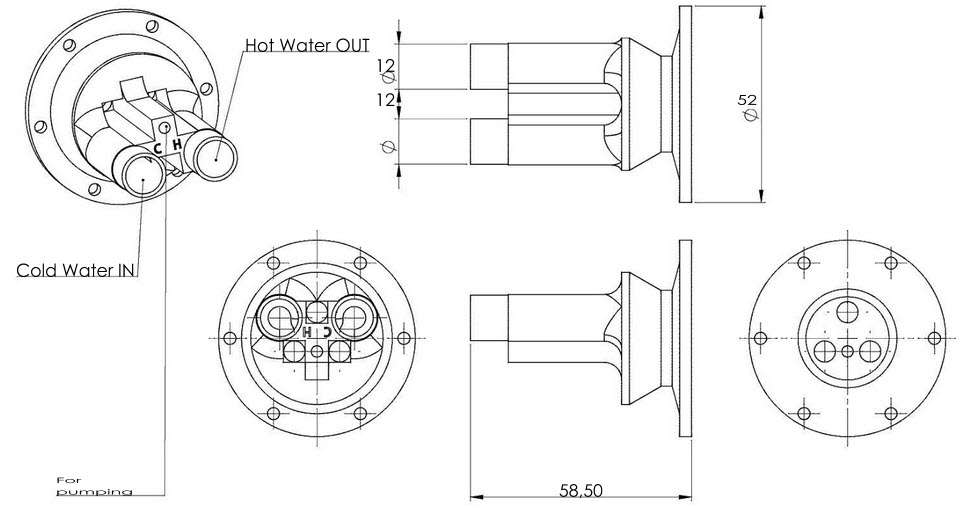
On the figure below, the rear of the whole device can be seen (non-binding image of the holder for illustration of the principle – the final device could be slightly different).
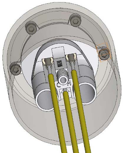
The alumina probe holder has been designed for the efficient cooling of the three E-field probes that are set in an equilateral configuration. The distance between two probes is 12 mm. The whole device is completely removable for maintenance and cleaning if necessary. The probe holder is attached to the PEEK sheath by 6 M3 PEEK screws.
PEEK Sheath
Aluminum Probe Holder Feed Through
The probe holder has one small pipe with a thermal insulating sheath and a vacuum valve to create a partial vacuum in the Dome.
There are two 5m long water pipes with thermal insulating sheaths for the water-cooling of the probe holder.
The three E-field probes fiber links inside the boiler will be fixed on the input water pipe between the pipe and its thermal insulating sheath. The feed-through device for the three E-field probes fiber links and the two water pipes is shown on next page (non-binding image of the holder for illustration of the principle – the final device could be slightly different).
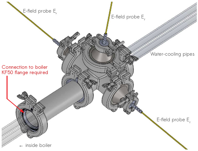
On this image the three probes fiber links are not represented, neither are the thermal insulating sheaths of the pipes. A KF50 flange is required to mount the HLD-vac-Cooler to the boiler. The HLD-vac-Cooler will extend 50mm inside the boiler.
To reduce water droplets adhesion on the PEEK surface, a specific treatment could be made to reduce the wettability of the PEEK by a specific treatment. This option is not included in this white paper, a low to ultra low wettability PEEK protective sheath could be an option if the adhesion of droplets is too high in practice as water present a shielding effect.
The probes will be calibrated in their operational configuration, mounted on their alumina holder with the PEEK protective sheath. Some time-domain simulations of the typical signals that will be obtained are given hereafter. For these simulations we have considered the sampling rate (2.5 GS/s) of the oscilloscope DPO3014.
Be aware that the following results are simulation results giving only the order of magnitude of the signals that will be obtained with the offered solution, the small expected effect of the PEEK protective sheath being not taken into account.
Simulation results with EL1-vac-SP10 and ET5-vac-SP10 probes and the three channels optoelectronic converter eoSense LF-3-SP-L3HA
Simulations of single shot 10 µs pulse with a carrier @ 6.78 MHz are given below with a peak E-field strength of 100 kV/m. Both temporal signal and its associated spectrum are shown. On the temporal response (left graphs), the vertical scale corresponds to the output voltage delivered by the optoelectronic converter LF-3-SP-L3HA covering the 100 kHz-10 MHz frequency range.
Top graphs correspond to ET5-vac-SP10 probes and bottom graphs to EL1-vac-SP10 probe.
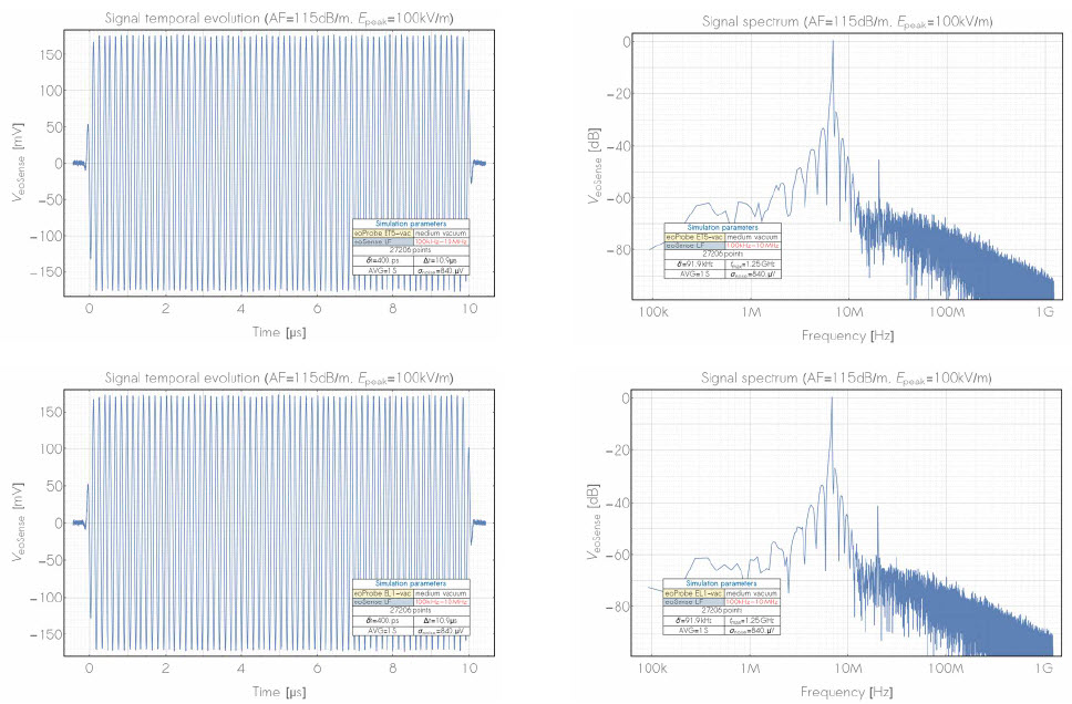
Both probes give roughly the same signal (- 300 mV peak-to-peak output for a 100 kV/m peak E-field strength. As seen, the raw signal (on the left) can be easily measured in single shot with an excellent SNR of – 60 dB (see spectrum on the right). At this high field strength, a very small non-linearity as we are approaching the 1dB compression point can be seen on the spectra (third harmonic between -40 to -45 dB @ – 20 MHz).
With much lower peak E-field strength (1 kV/m), it is necessary to make an average over 100 samples in order to keep a very good SNR (> 40 dB) as seen on the graphs of the next page.
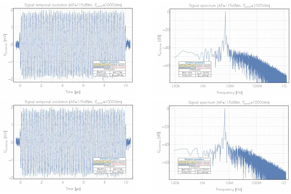
With a 1kV/m peak E-field strength, a ~ 4mV peak-to-peak signal will be obtain, covering half of output Tektronix DPO3014 dynamic range when it is set on its highest sensitivity.
Conclusion
In order to fulfill the stated requirements, two types of required E-field probes are required:
- The less sensitive longitudinal probe (EL1-vac-SP10) to avoid the saturation of the output signal at high field,
- The most sensitive transverse probe (ET5-vac-SP10) in order to make measurements with E field strength ranging between 100V/m to 200 kV/m.
The complete configuration for the Remote measurement of absolute E-Fields in a High Temperature Environment is provided below:
|
Remote Measurement in High Temperature |
|
|
|
Model No. |
Product Description |
QTY |
| eoSense Converter |
|
|
| LF-3-SP-L3HA | Triple channel optoelectronic converter 100kHz ↔ 10MHz frequency bandwidth 10MHz frequency bandwidth for specific purpose with selectable gain |
1 |
| eoProbe |
|
|
| ET5-vac-SP10 | High sensitivity E field probe for ultra low of high pressure gases. 10m fiber length |
2 |
| EL1-vac-SP10 | High speed longitudinal E field probe for ultra low of high pressure gases. 10m Fiber |
1 |
| Accessories |
|
|
| eoLink EXT25-R | Rugged optic link eoLink EXT25-R of 25 meters |
3 |
| HLD-vac-Cooler | Water-cooled PEEK-Alumina composite holder for 2 probes ETX-vac and 1 probe ELX-vac provided with two 5m heat insulated water pipes. Completely removable system with ISO KF-50 feed through |
1 |
| CALSS | LF-CAL-air-SP. Specific E field probe calibration in air with specific water cooled holder |
3 |
![]() Application Note: Remote Electric Field Measurement in a High Temperature Environment
Application Note: Remote Electric Field Measurement in a High Temperature Environment