KAPTEOS PRODUCT LINE
The Value and Benefits of Electro-optic Technology
Kapteos Products
• eoSense™ Optic to Electro Converter
• eoProbe™ to measure E-field (EMF)
•• eoCal™ – eoProbe Calibration
•• eoLink™ – 100m Fiber optic extension
•• eoPod™ – eoProbe Articulated Arm and Stand
Kapteos – On-Site Training
• Applications (Target Markets)
• Antennas – Measurement of E-fields Emitted by Antennas• NFACS (Near Field Antenna Characterization Solution)
• 3D NFACS (Near Field Antenna Characterization Solution)
• Vectorial & Characterization of Ultra Compact Antennas
• EMC -Measurement of E-Fields in Electromagnetic Compatibility
• EMP – Time-resolved measurements of Electromagnetic Pulse
• High Temperature – Measurement in High Temperature
• High Voltage – Measurement of E-fields in High Voltage
• Measuring the E-Field around a Laptop
• MRI – Measurement of E-fields inside an MRI
• Plasma – Measurement of E-fields inside Plasma
• SAR – Specific Absorption Rate (SAR) assessment
• Online Software Simulation Tool – Determine Online, before you purchase, the value of the Kapteos Solution!
• FAQ’s – A wealth of Information!
RELIANT EMC PRODUCT LINES
MANUFACTURERS
Request a Quote / Contact Us!
KAPTEOS MEASURE ABSOLUTE E-FIELD AROUND A LAPTOP
SUBJECT: MEASURE ABSOLUTE E-FIELD AROUND A LAPTOP EXPOSED TI HIGH ELECTRIC (E) FIELD STRENGTH
OBJETIVE:
The objective is to measure absolute E-field around a laptop exposed to high electric (E) field strength.
TESTING ENVIRONMENT:
1. The laptop is located inside a shielded room (Faraday cage and/or anechoic chamber) with an antenna radiating a CW (Continuous Wave).
2. The measurements are carried out in the frequency domain with an Automatic Spectrum Analyzer (ASA) or with a Vector Network Analyzer (VNA).
3. The distance from the shielded room to the control room in which the ASA or VNA is located is < 5 meters.
4. The frequency bandwidth of interest is 1 MHz ~ 18 GHz and the E-field strength of interest ranges from a few V/m up to 200kV/m.
5. The probes have to be calibrated as absolute E field strength measurement of a three E-field components are required.
OFFERED SOLUTIONS
In order to cover both E field strength of interest without any saturation and most of the frequency range of interest, two different type of probes are proposed:
1. High speed longitudinal probe eoProbe EL1-air for making measurements up to 200 kV/m without any saturation.
2. High speed transverse probe eoProbe ET1-air for making measurements up to 500 kV/m without any saturation.
The three probes are mounted on a specific dielectric holder eoPod LW-air in order to get the three components of the E field vector in a very small measurement volume < 1 cm3.
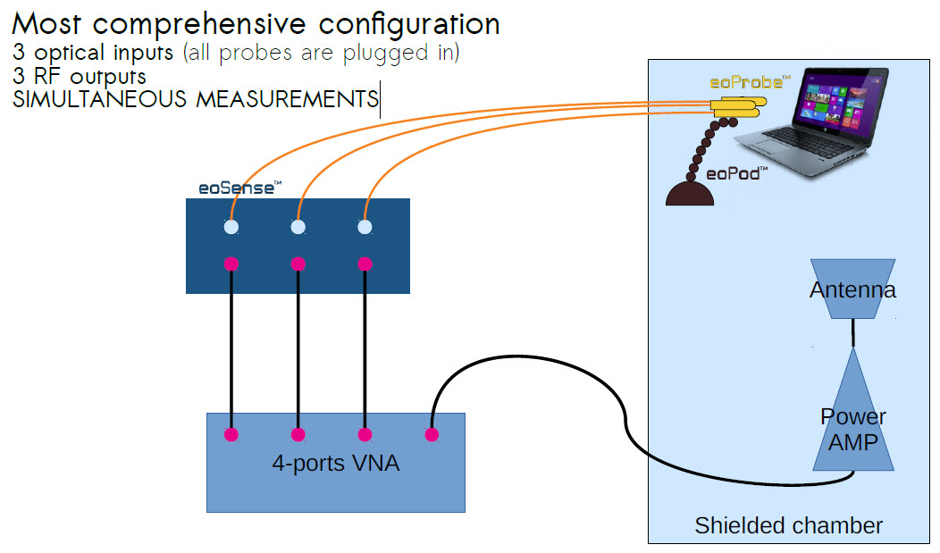
The proposed solution concerning the converter is to use three channels optoelectronic converter eoSense HF0.1-16-3 in order to be able to measure simultaneously the three components of the E field vector (thus requiring 3 ASA or a 4-port VNA).
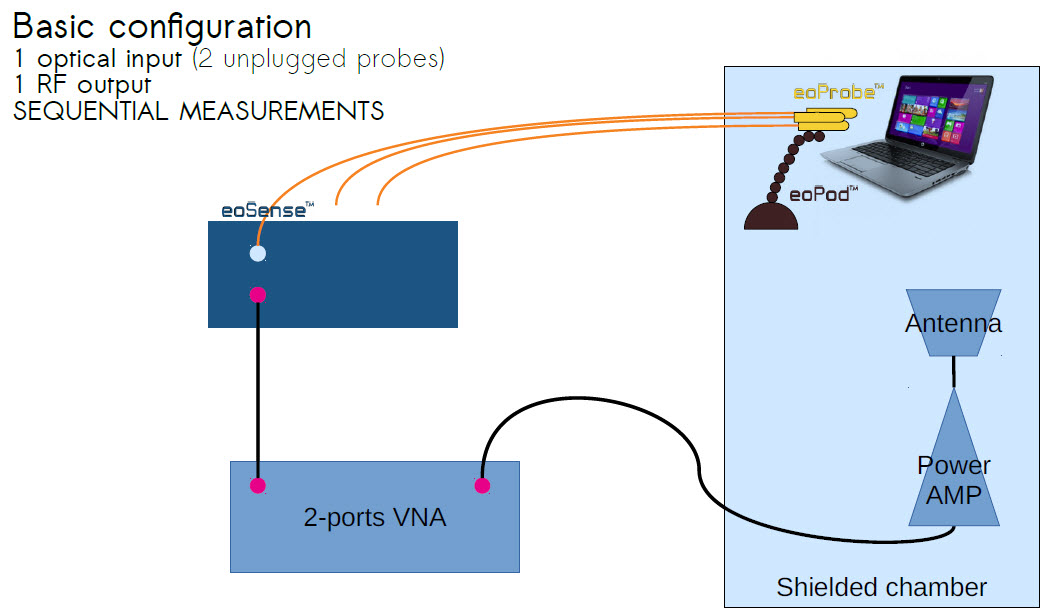
There is a less capable solution that consists of using a single channel optoelectronic converter eoSense HF0.1-16-1 and to connect the eoProbes during each interchange measurement in order to get sequentially the three components of the E field vector.
With such a solution, it is impossible to get automatic measurement as a human intervention is required to change the measurement from Ex component to Ey component and then to Ez component.
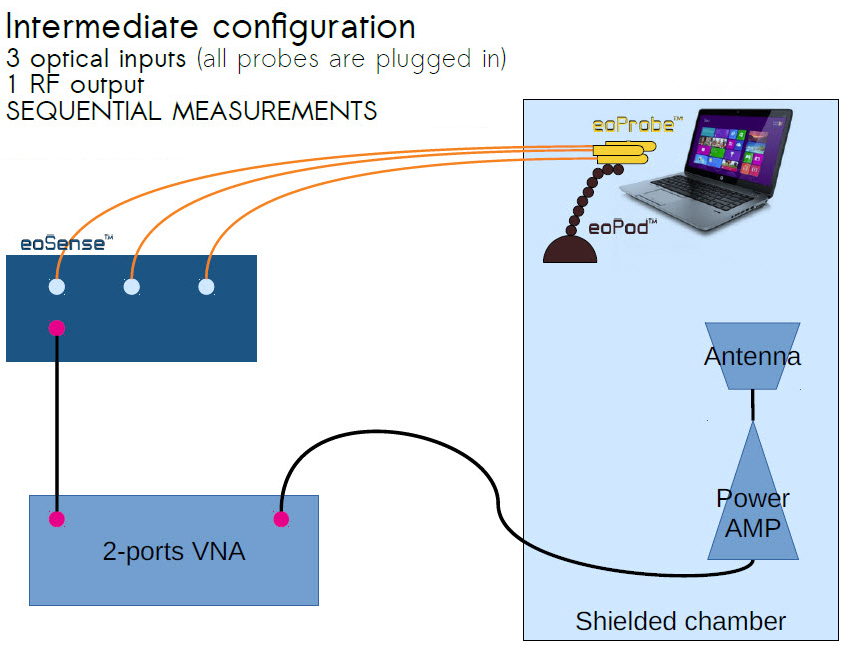
To avoid the issue described above, an intermediate solution is describe below with a single channel optoelectronic converter eoSense HF0.1-16-1 with an embedded optical switch (controlled via software) to automatically switch from the measurement of Ex component to Ey component and then to Ez component. This intermediate solution consists of the best trade-off between performances, capacity of automatic measurements and price.
The synoptic of the three solutions are given below from the entry level solution to the most comprehensive and effective solution.
BASIC CONFIGURATION
1 optical input (2 unplugged probes)
1 RF output
SEQUENTIAL MEASUREMENTS
INTERMEDIATE CONFIGURATION
3 optical inputs (all probes are plugged in)
1 RF output
SEQUENTIAL MEASUREMENTS
MOST COMPREHENSIVE CONFIGURATION
3 optical inputs (all probes are plugged in)