
COM-POWER PRODUCTS
• Company Overview
• Absorbing Clamps
• Antenna Kits
• Antennas
• CDNs
• Comb Generators
• Current Probes
• EM Clamps
• Emissions System
• Immunity System
• ISNs
• LISN
• Magnetic Field Generator
• Masts
• Near Field Probes
• Power Amplifiers
• Preamplifiers
• Spectrum Analyzers
• Surge Generators
• System Controllers
• Telecom Analyzer
• Telecom Test System
• Transient Limiters
• Tripods
• Turntables
• Data Sheets
RELIANT EMC PRODUCT LINES
MANUFACTURERS
Request a Quote / Contact Us!
Com-Power Current Probes
Current Probes Clamp on Current probes are used in EMC Testing for Emission and Immunity.
• Click here for a full description of Currnet Probe Clamps
• FCLC Series of Current Probe Calibration Fixtures
• Emissions Current Probes
• • CLCE-400 Current Probe for Emissions Measurement 10 kHz – 400 MHz
• • CLCE-452 Current Probe for Emissions Measurement 10 Khz to 400 MHz
• Immunity Current Probes
• • CLCI-100 Bulk Current Injection Probe 10 KHz to 100 MHz 61000-4-6, CISPR 16-1-2
• • CLCI-400 Bulk Current Injection Probe: For Immunity Testing 10 kHz to 400 MHz RTA/DO-160F, Mil-Std-461
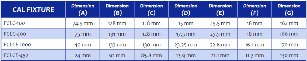
FCLC Series of Current Probe Calibration Fixtures
Models FCLC-100, FCLC-400, FCLCE-1000, FCLCE-452
CISPR, MIL-STD 461, DO-160


![]() Com-Power FCLC Series of Current Probe Calibration Fixtures Data Sheet
Com-Power FCLC Series of Current Probe Calibration Fixtures Data Sheet
CLCE-400 Current Probe for Emissions Measurement 10 kHz – 400 MHz
CISPR, MIL-STD 461, DO-160

The CLCE-400 RF Current Probe is part of Com-Power’s extensive line of radio frequency conducted emission/ immunity test equipment and calibration accessories. The CLCE-400 is suitable for compliance measurements required by CISPR 22, CISPR 32, DO-160, MIL-STD-461, etc, as well as for applied current monitoring during conducted immunity tests. Its design incorporates a split-core ferrite in a rugged, circular hinged enclosure; thereby allowing the probe to be opened on one side in order to easily place the wire(s), cable(s) or cable bundle(s) to be tested into the probe window, making the CLCE-400 much more convenient to use than other non-split core probes. The CLCE-400 is designed to be used in conjunction with a spectrum analyzer or EMI receiver or any 50? impedance measurement equipment, which measure magnitude quantities in terms of true rms voltage.
Specifications:
- · Frequency Range: 10 kHz to 400 MHz
- · Window (Aperture) Inside Diameter: 1.25″ (32 mm)
- · Outside Diameter: 2.83″ (72 mm)
- · Height: 0.76″ (19.3 mm)
- · Weight: 0.275 lbs. (0.125 kg)
- · Connector: Type-N (Female)
- · Transfer impedance (ZtΩ): 7Ω*
- · Transfer impedance (dBΩ): -25 to 19 dBΩ (typical)*
- · Max Primary Current (DC-400 Hz): 100 Amps
- · Max Primary Current (RF): 4 Amps
- · Max. Core Temperature: 248℃F (120°C)
- · Related Accessories Available from Com-Power:
- FCLCE-1000 Calibration Fixture
- TEP-050 50Ω Terminator
- SPA-815TGE Spectrum Analyzer
![]() Com-Power CLCE-400 Current Probe Data Sheet
Com-Power CLCE-400 Current Probe Data Sheet
![]() Com-Power CLCE-400 Current Probe Manual
Com-Power CLCE-400 Current Probe Manual
CLCE-452 Current Probe for Emissions Measurement 10 Khz to 400 MHz

The CLCE-452 RF Current Probe is part of Com-Power’s extensive line of radio frequency conducted emission/ immunity test equipment and calibration accessories. The CLCE-452 was designed to accommodate thick cable bundles(s), up to two inches in diameter. It is suitable for compliance level conducted emissions/ disturbance current measurements, such as those required by CISPR 22, CISPR 32, RTCA DO-160 and MILSTD-461 standards, to name just a few. The CLCE-452 incorporates a split-core ferrite into its rugged, circular enclosure. The probe enclosure is hinged, allowing the probe to be opened on one side in order to easily place the wire, cable(s) or cable bundle(s) to be tested into the probe window. This makes the CLCE-452 much more convenient to use than other non-split core probes.
Specifications:
- · Product: RF Current Probe
- · Frequency Range: 10 kHz to 400 MHz
- · Transfer Impedance (typical): 0.25 to 3 ohms (-12 to 8 dBΩ)
- · Standard(s): MIL-STD-461, RTCA DO-160D, CISPR 16, CISPR 22, CISPR 32, etc.
- · Impedance: 50Ω (nominal)
- · Coaxial RF Connector: N-type (female)
- · Dimensions (H)x(W)x(D): 4.9” x 1.4” x 5.9” (125 x 36 x 150 mm)
- · Probe Window Diameter: 2” (52 mm)
- · Weight: 1.5 lbs (0.68 kg)
- · Operating Temperature: 40° F to 104° F (5° C to 40° C)
- · Accessories Available from Com-Power:
·· FCLCE-452 Calibration Fixture
·· CLCI-series Bulk Current Injection Probes
·· ACS-Series Power Amplifiers
![]() Com-Power CLCE-452 RF Current Probe Data Sheet
Com-Power CLCE-452 RF Current Probe Data Sheet
![]() Com-Power CLCE-452 RF Current Probe Manual
Com-Power CLCE-452 RF Current Probe Manual
Current Injection Probes For RF Conducted Immunity Testing Com-Powers Current Injection Probes are used for RF conducted immunity testing per IEC 61000-4-6, CISPR 16-1-2, RTCA DO-160 and MIL-STD 461. Current injection Probes are to be used only when there is no commercially available CDN for the type of port(s) to be tested. Contact Us The principal use of the probe is to inductively couple large amount of RF current into the cables of the Equipment Under Test (EUT) to determine its susceptibility. When choosing a Current Injection Probe the most important feature is the internal diameter or «window». This window must be able to accommodate the cable and wires under test. The probe incorporates split-core ferrites into its rugged, circular enclosure, and is hinged; thereby allowing the probe to be opened on one side in order to easily place the wire, cable(s) or cable bundle(s) to be tested into the probe window, making it much more convenient to use than other non-split core probes. Current probes are calibrated through the use of a calibration fixture with a coaxial-type arrangement. The fixture allows the probe to be clamped around the center conductor, while the outer conductor encapsulates the probe on four sides, so that the transmission line characteristics are not compromised. This fixture is available separately.
CLCI-100 Bulk Current Injection Probe 10 KHz to 100 MHz 61000-4-6, CISPR 16-1-2

For IEC 61000-4-6 and CISPR 16-1-2 The CLCI-100 Bulk Current Injection Probe is part of ComPower’s extensive line of radio frequency conducted immunity test equipment and calibration accessories; geared specifically to comply with the requirements contained in IEC 61000-4-6 and CISPR 16-1-2. The CLCI-100 incorporates split-core ferrites into its rugged, circular enclosure, and is hinged; thereby allowing the probe to be opened on one side in order to easily place the wire, cable(s) or cable bundle(s) to be tested into the probe window, making the CLCI-100 much more convenient to use than other non-split core probes. The efficiency of the CLCI-100 probe enables it to achieve test levels up to 10 Vrms across its frequency band with less than 100 watts forward power. The probe can handle up to 100 amps «window current» on its secondary, and up to 100 watts RF input power to its primary. An RF Current probe is typically used in conjunction with spectrum analyzer or EMI receiver, which measure magnitude quantities in terms of true rms voltage. The Transfer Impedance conversion factor, which is expressed in terms of dB over 1?, converts the voltage quantity into a current quantity, expressed in terms of dB over 1 uA.
Specifications:
- · Frequency Range: 10 KHz to 100 MHz
- · Window Inside Diameter: 1.575” (40 mm)
- · Outside Diameter: 5.75” (70 mm)
- · Width: 2.75” (70 mm)
- · Weight: 4.5 lbs. (2.04 kg)
- · Input Connector: Type-N (female)
- · Max Input Power: 100 Watts (continuous)
- · Turns Ratio: 1:1
- · Max. Core Temperature: 140 °C – 284 °F
- Accessories Available from Com-Power for setting test levels and running the test:
- · ·FCLC-100 Calibration Fixture
- · ·ADA-515-2 150 ohms to 50 ohms Adapters
- · ·Term-50-100W Power Terminator ASC series Power Amplifiers
- · ·ACS Series Power Amplifiers
![]() Com-Power CLCI-100 Bulk Current Injection Probe Data Sheet
Com-Power CLCI-100 Bulk Current Injection Probe Data Sheet
![]() Com-PowerCLCI-100 Bulk Current Injection Probe Manual
Com-PowerCLCI-100 Bulk Current Injection Probe Manual
• • CLCI-400 Bulk Current Injection Probe: For Immunity Testing 10 kHz to 400 MHz RTA/DO-160F, Mil-Std-461
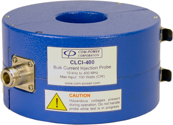
The CLCI-400 Bulk Current Injection Probe is part of ComPower’s extensive line of radio frequency conducted immunity test equipment and calibration accessories; geared specifically to comply with the requirements contained in RTA/DO-160F, Mil-Std-461. The CLCI-400 incorporates split-core ferrites into its rugged, circular enclosure, and is hinged; thereby allowing the probe to be opened on one side in order to easily place the wire, cable(s) or cable bundle(s) to be tested into the probe window, making the CLCI-400 much more convenient to use than other non-split core probes The efficiency of the CLCI-400 probe enables it to achieve test levels up to 10 Vrms across its frequency band with less than 100 watts forward power. The probe can handle up to 100 amps «window current» on its secondary, and up to 100 watts RF input power to its primary. An RF Current probe is typically used in conjunction with spectrum analyzer or EMI receiver, which measure magnitude quantities in terms of true rms voltage. The Transfer Impedance conversion factor, which is expressed in terms of dB over 1?, converts the voltage quantity into a current quantity, expressed in terms of dB over 1 uA.
-
Specifications:
· Frequency Range: 10 kHz to 400 MHz
-
· Complies with RTCA/DO-160, Mil-Std-461
-
· Current Injection & Monitoring capability
-
· Three-year warranty
-
· Window (Inside) Diameter: 1.575″ (40 mm)
-
· Outside Diameter: 5.75″ (146 mm)
-
· Width: 2.75″ (70 mm)
-
· Weight: 4.5 lbs. (2.04 kg)
-
· Input Connector: Type-N (female)
-
· Max. Input Power: 100 Watts (continuous)
-
· Turns Ratio: 1:1
-
· Max. Core Temperature: 110° C – 230° F
-
· Accessories Available from Com-Power for setting test levels and running the test:
-
· · FCLC-100 Calibration Fixture
-
· · Term-50-100W Power Terminator ASC series Power Amplifiers
![]() Com-Power CLCI-400 Bulk Current Injection Probe Data Sheet
Com-Power CLCI-400 Bulk Current Injection Probe Data Sheet
![]() Com-Power CLCI-400 Bulk Current Injection Probe Manual
Com-Power CLCI-400 Bulk Current Injection Probe Manual
Current Probes Clamps
Conducted Noise emissions measurements using a clamp on current probe: Conducted noise can be measured using an LISN (for power lines) or ISN (for signal lines), however, these techniques require that we first open the corresponding power or signal cable and insert the LISN or ISN in the path. The alternate method using a Clamp On Current Probe does not require us to open the cable to insert the LISN or ISN in the cable connection path. Instead, we simply clamp on the current probe on to the cable. For obvious reasons, such a probe is constructed using two halves of a toroidal magnetic material hinged together on one side to allow clamping on to a cable under test. Conducted noise in the cable is then measured by the cable under test forming the primary winding of a current transformer. The secondary winding of this current transformer is wound around the magnetic material. The current measured in the secondary winding reflects the current flow in the primary winding (the cable under test). The current clamp can also be used to inject noise on to a cable in the system under test for immunity (or susceptibility). In this case, the noise to be injected is on the primary of the current transformer and is wound around the split ferrite core of the clamp on probe. The secondary winding is the cable under test. This method is also a convenient alternative to using a CDN (coupling decoupling network) which requires that you open the cable circuit and insert the appropriate CDN. It is important to note that the design of the injection current probe would be different than the emissions probe because the immunity test currents are generally much higher test levels. Each type of probe would also require that it be designed to perform the specific current level, frequency of operation, etc. Current probes are calibrated through the use of a calibration fixture with a coaxial-type arrangement. The fixture allows the probe to be clamped around the center conductor, while the outer conductor encapsulates the probe on four sides so that the transmission line characteristics are not compromised. This fixture is available separately.